Marble Clock RTC


File stampabili (16)
-
 stl
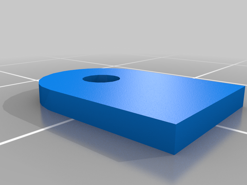
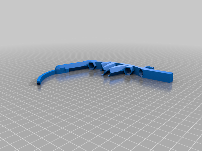
stltab_reinforcement.stl
10 Ko · 557 download
-
 stl
stlTab_1.5mm.stl
9 Ko · 561 download
-
 stl
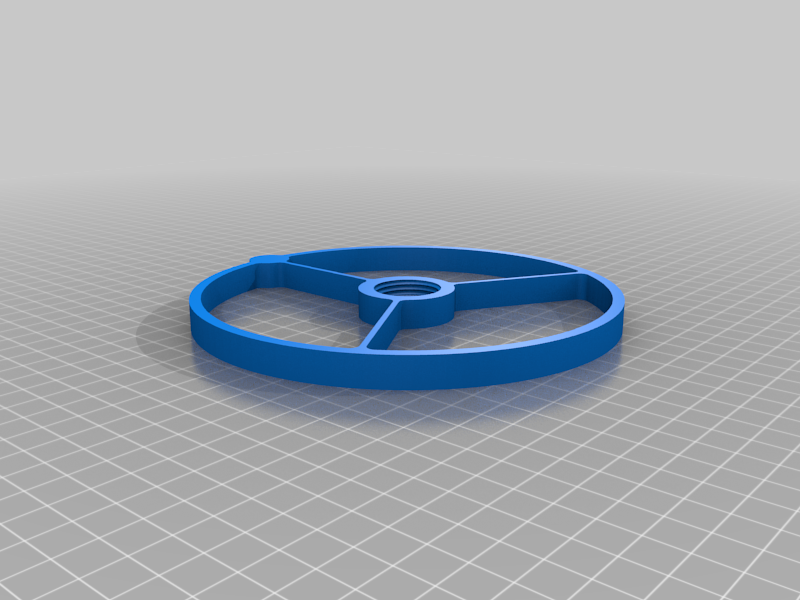
stlwheel.stl
159 Ko · 533 download
-
 stl
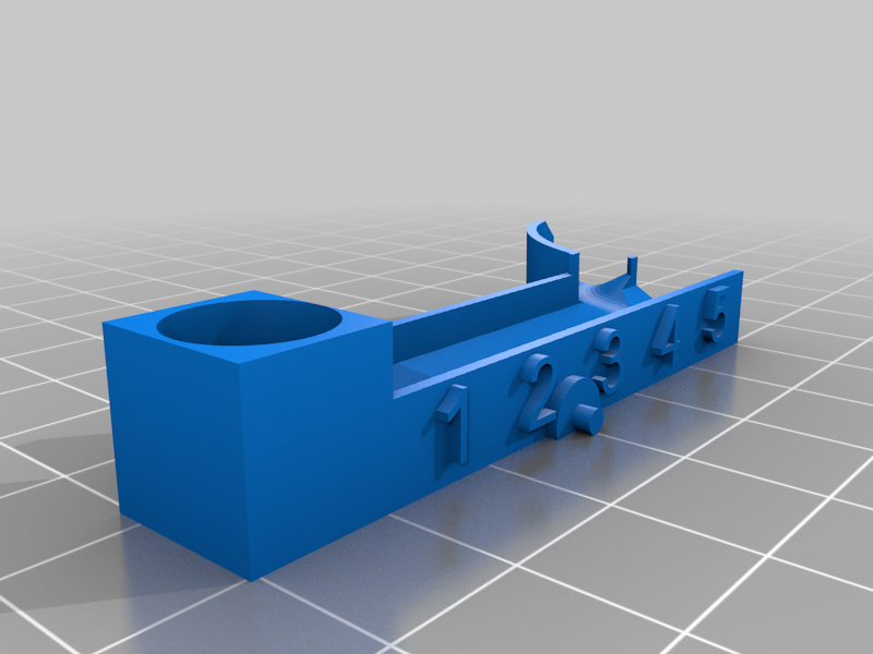
stlmotor_mount.stl
227 Ko · 534 download
-
 stl
stlinput_tower.stl
183 Ko · 533 download
-
 stl
stltens_tray.stl
246 Ko · 532 download
-
 stl
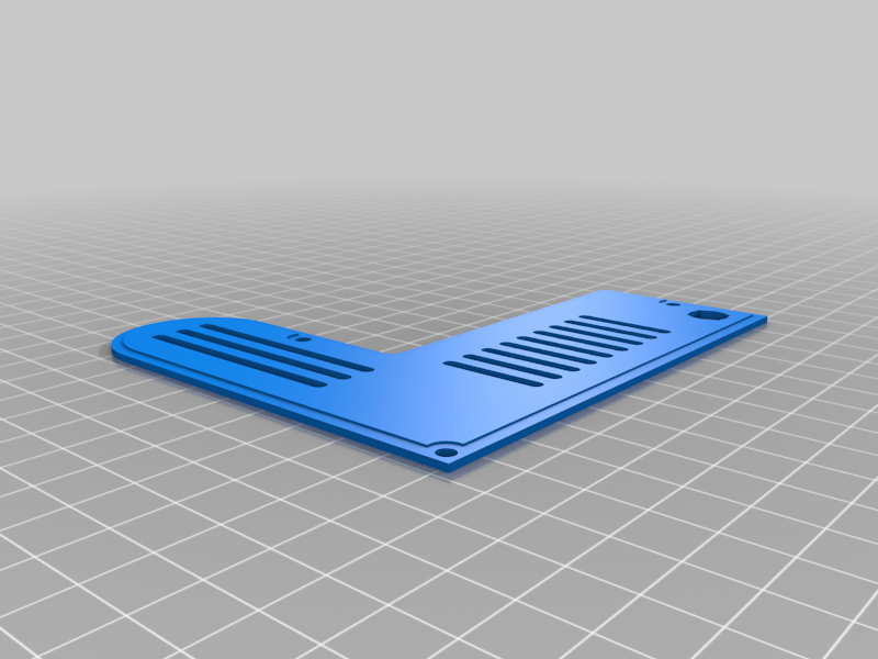
stlback.stl
112 Ko · 531 download
-
 stl
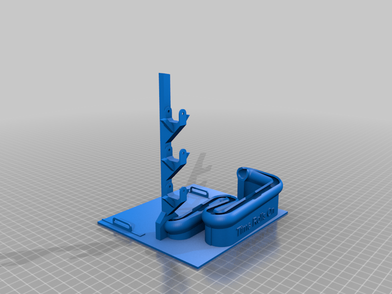
stlclock_base.stl
1.2 Mo · 532 download
-
 stl
stlhours_tray.stl
284 Ko · 533 download
-
 stl
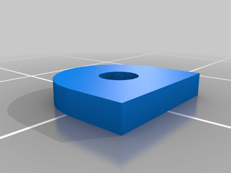
stlReinforcer.stl
3 Ko · 557 download
-
 stl
stlshell.stl
194 Ko · 532 download
-
 stl
stlminutes_tray.stl
268 Ko · 531 download
-
 stl
stlTab_2mm.stl
9 Ko · 559 download
-
 stl
stlOpen_Shell_2.stl
94 Ko · 561 download
-
 stl
stlball_return.stl
181 Ko · 531 download
-
 stl
stlbase2.stl
1.9 Mo · 560 download
Descrizione
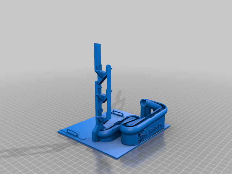
This is a redesign of the electronics for the Marble Clock "Time Rolls On" by HFoG on Thingiverse: https://www.thingiverse.com/thing:4891112
Follow the instructions there to print and assemble the printed parts of this clock.
I did add an "Open Shell 2.stl" which provides an alternate for the electronics enclosure used in the original. Use this or shell.stl as suits your taste. I like to see the electronics.
This version adds a DS3231 real-time clock (RTC) module which uses a crystal oscillator to keep time instead of using the Arduino Nano built-in oscillator for timing. I used a DS3231SN which has a temperature-stabilized crystal oscillator but any DS3231 should work.
Adding the RTC requires three connections to the Nano, plus +5V power and ground. The SDA and SCL pins on the SD3231 connect to the Arduino I2C pins (pins A4 and A5 on the Nano) for control, and the SQW (square wave output) pin connects to the D3 pin on the Nano to provide a once-per-second interrupt for a tick count. The Adafruit RTClib library is used to initialize the RTC in the code.
Several pins on the DRV8825 that were tied to Arduino pins in the original design have been changed in this circuit as no program control of those pins is needed. M0, M1, M2 and SLP inputs on the DRV8825 are tied directly to +5V. This enables the driver chip and sets it to 32 microsteps per step for smooth and quiet operation just as they were set using the Arduino in the original design.
The DIR pin on the DRV8825 is intentionally not connected. This selects the correct direction for my stepper. You can tie it to +5V if you find your stepper turning the wrong direction.
You will need to compile the new sketch (Arduino source code) and upload to the Nano. This sketch uses the RTC 1Hz square wave output as an interrupt to provide an accurate once-per-second tick. This is used to advance the stepper one full revolution over the course of 60 ticks.
Include the Adafruit RTClib library when compiling the updated sketch. (In the Arduino IDE menu select Sketch, Include Library, Manage Libraries and search for RTClib. Install the Adafruit verson).
The "stepspeed" value in the sketch sets how fast each tick moves the dial. Larger numbers provide slower movement. I prefer a distinct tick motion which the default value of 700 provides. If you prefer smooth rotation change this value to 4500.