Insect bite force sensor forceX v.1
 von Peter_TR


Druckbare Dateien (12)
-
 stl
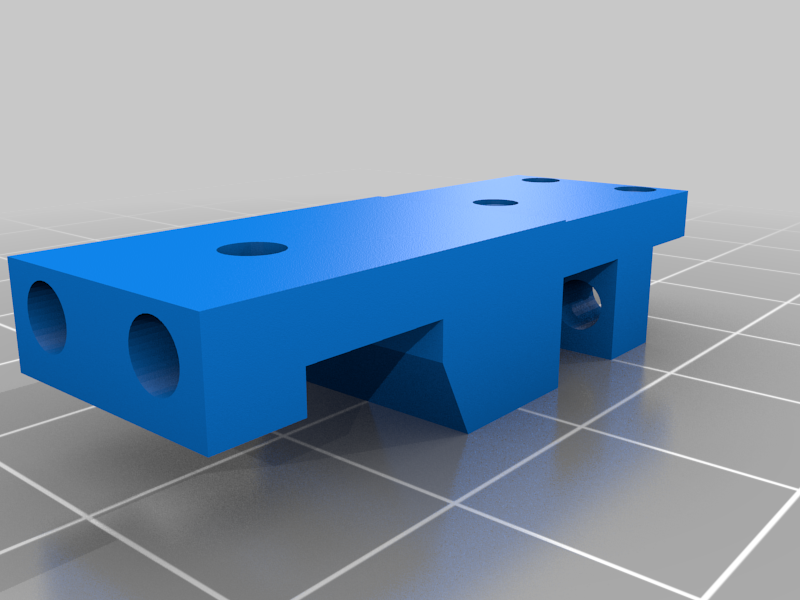
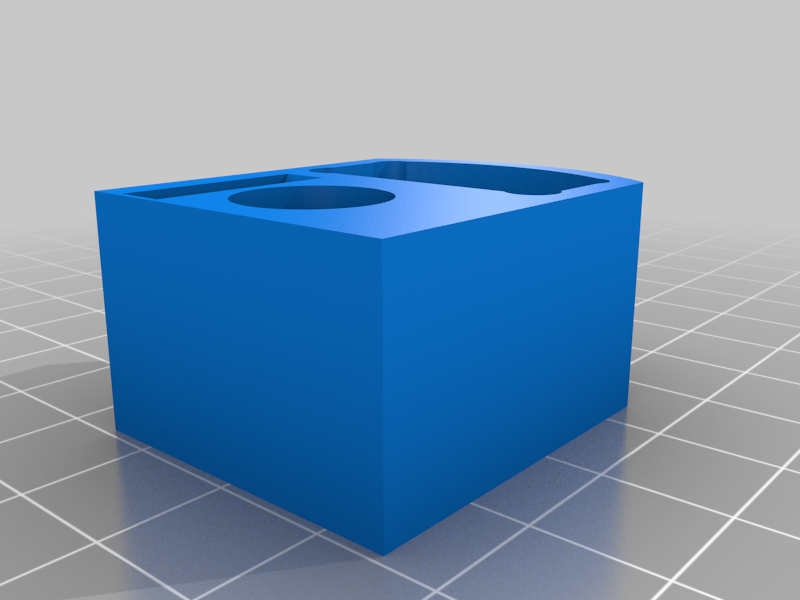
stlmain_body.stl
351 Ko · 130 Downloads
-
 stl
stlbottom_tip_element_holder.stl
50 Ko · 123 Downloads
-
 stl
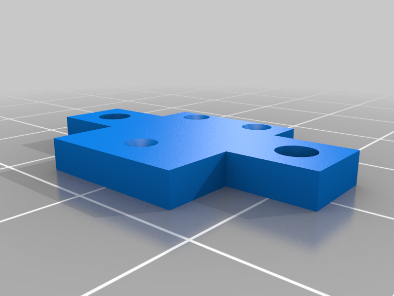
stllever.stl
108 Ko · 124 Downloads
-
 stl
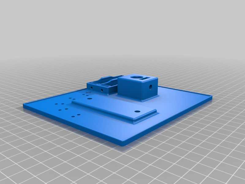
stlbase_plate.stl
1 Mo · 120 Downloads
-
 stl
stlmiscroscope_flange.stl
182 Ko · 118 Downloads
-
 stl
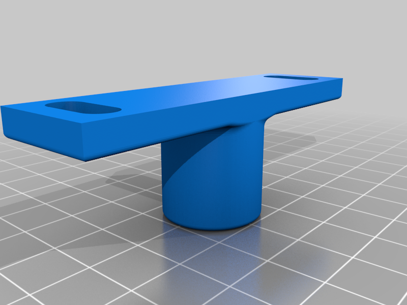
stlmicroscope_slider.stl
95 Ko · 121 Downloads
-
 stl
stlcam_holder_back.stl
76 Ko · 119 Downloads
-
 stl
stlrod_connector_x2.stl
75 Ko · 121 Downloads
-
 stl
stlrod_cam_connector.stl
65 Ko · 118 Downloads
-
 stl
stlM5_knob_x7.stl
157 Ko · 121 Downloads
-
 step
stepforceX_v1_3D_print.step
28.6 Mo · 101 Downloads
-
step
forceX_v1_metal_turn.step
398 Ko · 88 Downloads
Beschreibung
(3D-printed v.1)
I. Resources and further reading
The forceX setup is a reproducible advancement of the design introduced by Herrel et al. (1999) and was published in the following article:
The ‘forceR’ package for closing force analyses (written in the programming environment R (R Core Team, 2021)) is available at CRAN.
A video of the assembly instructions is available on Youtube:
https://youtu.be/xabIewPMVuU
II. Parts lists for forceX measurement unit
Table 1: 3D-printed components. All components should be printed in PLA filament, since this material is less flexible than other common materials like ABS, ASA or PETG.
componentamountbase plate1main body1lever1microscope flange1microscope slider1bottom tip element holder1cam holder back1rod connector2rod cam connector1M5 knob7Table 2: Generic components.
componentamountM1 bolt 3 mm6M1 hex nut6M2 threaded rod 16 mm1M2 hex nut1M2 bolts (from microscope)3M2 washers (from microscope)3M3 bolt 16 mm10M3 hex nut5M5 hex bolt 20 mm4M5 hex nut2M5 wing nut2M5 washer212 mm diameter rod (e.g. aluminum pipe)s.b.AA battery2flexible cable (1-core & 2-core)The 12 mm diameter rod should be cut into the following pieces:
- main rod: 90 mm
- microscope rod: 100 mm
- camera module rods: depending on focal range of camera. We used two 100 mm rods for a 5-MP RPi Camera (B) rev. 2.0 with adjustable focus (Waveshare, Shenzhen, China).
Table 3: Off-the-shelf and custom components.
componentamountKistler 9215A1Kistler 1651C11microscope (e.g. Bresser Junior Stereo 3D)1tip element2III. Parts list for power source
Table 4: Parts lists for power source.
componentamountbox1banana jack32-way toggle switch (e.g. Eledis 1A series)1LED: red, 3 mm, 3V, 15mA1resistor: 9.1 kΩ19 V battery clip connector49V battery41-core flexible cableIV. Parts list for charge amplifier
For the parts list of the analog charge amplifier see IX. Schematics of custom electronics: Charge amplifier. For help in building this device, please contact M. Dübbert (Scientific Electronics & Experimental Design, Group of Prof. Büschges, University of Cologne).
V. Additional parts
Table 6: Additional parts list.
componentamountLabJack U3-HV1cable: circular 3-pin connector plug (e.g. GTX12-3) to 3 x male banana plugs1cable: BNC connector to 2-threaded wire1cable: USB type-A to USB type-B1VI. Assembly instructions
The following pages will guide you through the assembly of the forceX measurement system. At the end of this document you will find overview drawings of the whole setup and photos of additional components such as the custom charge amplifier and power source.
Step 1
partamounttypemain body1printedM3 bolt 16 mm1genericScrew the M3 bolt into the main body. The bolt will act as the fulcrum for the lever.
→Step 2
partamounttypebottom bite plate holder1printedM1 bolt 3 mm3genericM1 hex nut3generictip element1customInsert the M1 hex nuts into the recesses on the lower side of the bottom tip element holder using a soldering iron. Then, use the M1 bolts to fasten the tip element to the bottom tip element holder. Make sure to hand-tighten the bolts so that the tip element does not bend.
→Step 3
partamounttypeM3 bolt 16 mm2genericM3 hex nut2genericInsert the M3 hex nuts to the main body and tighten the bottom tip element holder to using the M3 bolts.
→Step 4
partamounttypeKistler 1651C11proprietaryKistler 9215A1proprietaryM2 threaded rod 16 mm1genericM3 bolt 16 mm2genericM3 hex nut2genericInsert the Kistler 9215A force transducer into the hexagonal hole in the main body. Use the M3 bolts and M3 hex nuts to secure the force transducer in place. Insert the M2 threaded rod into the force transducer. Attach the Kistler 1651C1 cable to the force transducer.
→Step 5
partamounttypelever1printedM1 bolt 3 mm3genericM1 hex nut3genericM2 hex nut1genericM3 bolt 16 mm4generictip element1customScrew the M3 bolts into the lever. These add stability to the lever and prevent bending. Attach the second tip element using the M1 bolts and hex nuts as described in Step 2. Place the lever on the main body and secure the M2 hex nut on the M2 threaded rod in the force transducer. The position of this nut on the rod defines the rotation of the lever and thus the gape distance at the tip elements.
→Step 6
partamounttypebase plate1printedmain rod 90 mm1genericInsert the main rod (e.g., a 90 mm piece of a hollow, aluminum rod with a dimater of 12 mm), into the base plate and attach the main body on its upper side.
→Step 7
partamounttypeM3 bolt 16 mm1genericM3 hex nut1genericUse the M3 bolt and hex nut to secure the main body on the main rod.
→Step 8
partamounttypeM5 knob1printedM5 hex bolt 20 mm1genericM5 hex nut1genericInsert the head of the M5 bolt into the 3D-printed M5 knob using a soldering iron. Use the M5 bolt assembly and the M5 hex nut to secure the main rod on the base plate.
→Step 9
partamounttypemicroscope flange1printedM5 hex bolt 20 mm2genericM5 washer2genericM5 wing nut2genericmicroscope rod 100 mm1genericAttach the microscope rod (e.g., a 100 mm piece of a hollow, aluminum rod with a dimater of 12 mm) to the microscope flange. Use the M5 bolts, washers and wing nuts to attach the microscope flange to the base plate.
→Step 10
partamounttypemicroscope slider1printedM5 knob1printedM5 bolt 20 mm1genericM5 hex nut1genericAttach the M5 knob to the M5 bolt as described in Step 8. Attach the microscope slider to the main rod and use the M5 bolt assembly to secure the slider in place.
→Step 11
partamounttypebattery connection wire1genericTake a short, one-stranded piece of electrical wire and wind it around the base plate battery holder outer holes so that the poles of the batteries will be connected.
→Step 12
partamounttypebattery to microscope cable1genericTake a two-cored piece of cable and wind one strand each around the base plate battery holder inner holes at the 'plus' and 'minus' signs, respectively.
→Step 13
partamounttypemicroscope1proprietaryM2 microscope bolts3genericM2 microscope washers3genericScrew the microscope (we used a Bresser Junior Stereo 3D) to the microscope slider. Make sure that the microscope cable slides through the big hole of the slider. Use the M2 bolts and washers of the microscope to fasten it on the slider. Connect the two strands of the cable of Step 12 to the microscope cable s, observing polarity.
→Step 14
partamounttypeAA battery2genericSlide the two AA batteries into the base plate battery holders, observing polarity as indicated by the 'plus' and 'minus' signs on the base plate. Once the batteries are in place, the microscope LED should automatically switch on.
→Camera module
Note that the above description does not yet show the camera module. However, we think that the following figure should help in setting it up. Python code to run the camera on Raspbian is available on Zenodo: .
VII. Schematics of forceX measurement unit
Overview
Exploded view and component names
ItemPart NumberTypeItemPart NumberType1Main bodyprinted36M1 hex nutgeneric4Base plateprinted37M1 bolt 6mmgeneric6Miscroscope flangeprinted38Upper tip elementcustom7Microscope rod 100 mmgeneric39M1 bolt 6mmgeneric8Microscope sliderprinted40M1 hex nutgeneric9Microscopeproprietary41M1 bolt 6mmgeneric10Lower tip element holderprinted42M1 hex nutgeneric11Main rod 90 mmgeneric43M1 hex nutgeneric12Lower tip elementcustom44M1 bolt 6mmgeneric13M5 knobprinted45M1 bolt 6mmgeneric14M3 bolt 16 mmgeneric46M1 hex nutgeneric15M3 bolt 16 mmgeneric47M1 bolt 6mmgeneric16M3 bolt 16 mmgeneric48M1 hex nutgeneric17M3 bolt 16 mmgeneric49M2 threaded rod 16 mmgeneric18M3 hex nutgeneric50M2 hex nutgeneric19M3 hex nutgeneric51M2 bolt (from microscope)generic20M3 hex nutgeneric52M2 washer (from microscope)generic21M5 hex boltgeneric53M2 washer (from microscope)generic22M5 wing nutgeneric54M2 bolt (from microscope)generic23M5 washergeneric55M2 washer (from microscope)generic24M5 washergeneric56M2 bolt (from microscope)generic25M5 wing nutgeneric64KISTLER 9215Aproprietary26M5 hex boltgeneric65Kistler 1651Cproprietary27M5 hex nutgeneric66Battery connection wiregeneric28M5 hex boltgeneric70Cable batteries to microscopegeneric29M5 hex boltgeneric71Cable mircoscopegeneric30M5 hex nutgeneric72AA batterygeneric31M5 knobprinted73AA batterygeneric32M3 bolt 16 mmgeneric74Leverprinted33M3 hex nutgeneric75M3 bolt 16 mmgeneric34M3 hex nutgeneric76M3 bolt 16 mmgeneric35M3 bolt 16 mmgeneric77M3 bolt 16 mmgenericProjected views (all directions)
VIII. Schematics of tip elements and exemplary edge shapes
IX. Additional diagrams and photos
Charge amplifier for piezo-electric force transducer
The plus pole thread of the 2-threaded wire coming from the BNC output of the amplifier is attached to the LabJack with the screw at AIN0, and the negative pole wire at the GND screw. Make sure the wires don't touch each other to prevent a short circuit.
Power source
Full setup
References- Herrel, A., Spithoven, L., van Damme, R., & de Vree, F. (1999). Sexual dimorphism of head size in Gallotia galloti: Testing the niche divergence hypothesis by functional analyses. Functional Ecology, 13(3), 289–297. https://doi.org/10.1046/j.1365-2435.1999.00305.x
- R Core Team. (2021). R: A language and environment for statistical computing. R Foundation for Statistical Computing. R Foundation for Statistical Computing. http://www.R-project.org