
Ball and Socket Mounting System - Revised
 von DrDean


Druckbare Dateien (26)
-
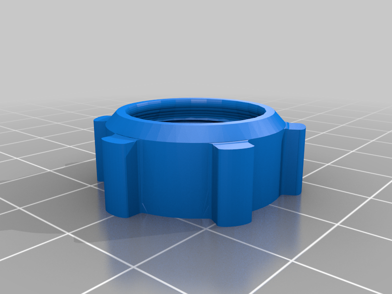 stl
stllocking_Nut.stl
806 Ko · 297 Downloads
-
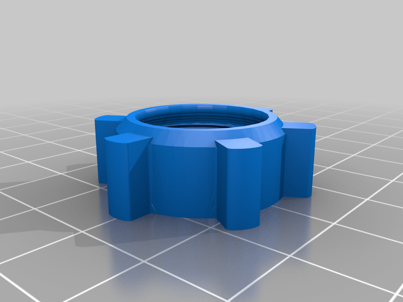 stl
stlLocking_Nut_-_Medium_Wheel.stl
808 Ko · 271 Downloads
-
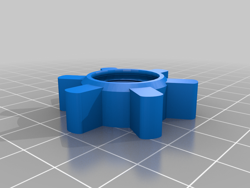 stl
stllocking_Nut_-_Large_Wheel.stl
869 Ko · 267 Downloads
-
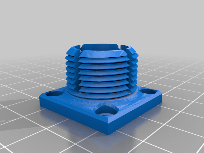 stl
stlSocket_flange.stl
393 Ko · 283 Downloads
-
 stl
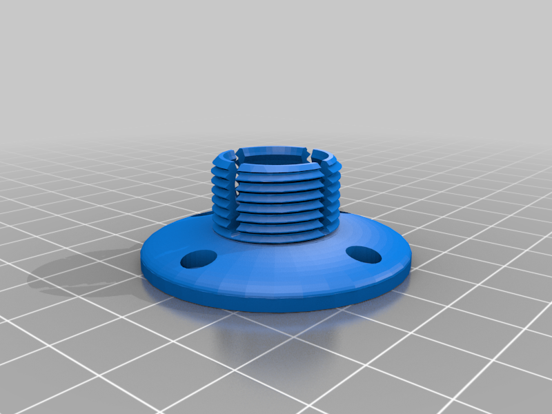
stlSocket_flange_Round_4_Holes.stl
466 Ko · 276 Downloads
-
 stl
stlSocket_flange_Round_6_Holes.stl
502 Ko · 273 Downloads
-
 stl
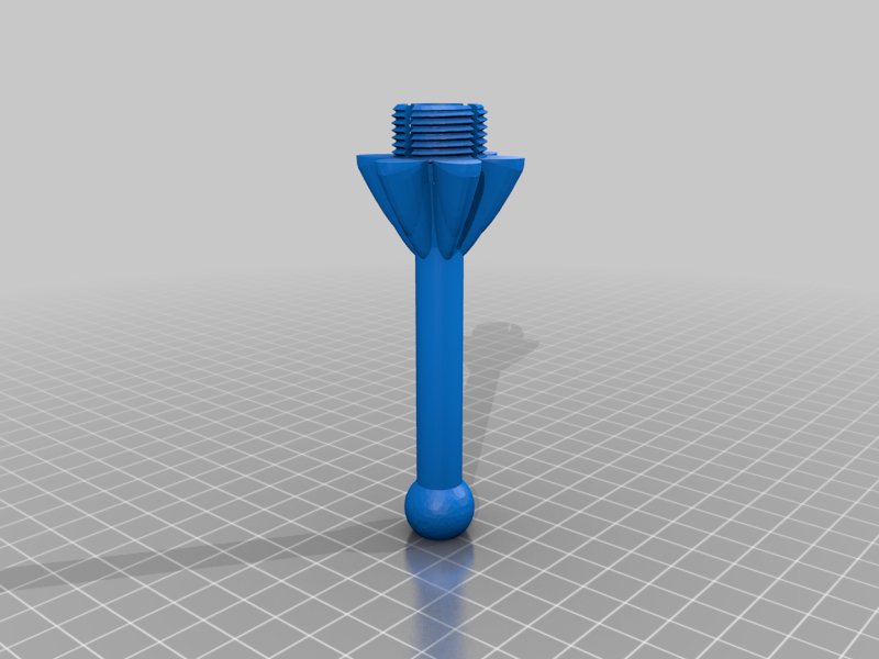
stlIntermediary_Socket_-_Extra_Long_-_Large_fins.stl
4.4 Mo · 257 Downloads
-
 stl
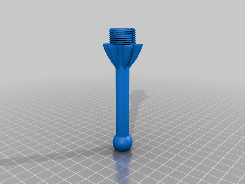
stlIntermediary_Socket_-_Extra_Long_-_Medium_fins.stl
413 Ko · 257 Downloads
-
 stl
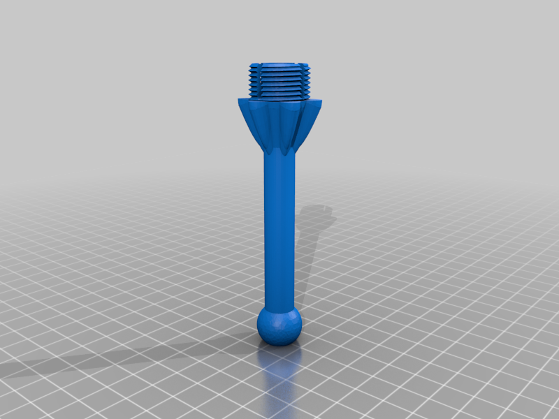
stlIntermediary_Socket_-_Extra_Long_-_Small_fins.stl
577 Ko · 258 Downloads
-
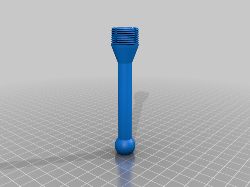 stl
stlIntermediary_Socket_-_Extra_Long.stl
424 Ko · 263 Downloads
-
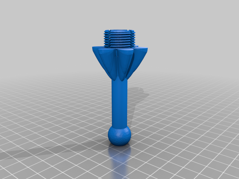 stl
stlIntermediary_Socket_-_Long_-_Large_fins.stl
4.5 Mo · 259 Downloads
-
 stl
stlIntermediary_Socket_-_Long_-_Medium_fins.stl
562 Ko · 260 Downloads
-
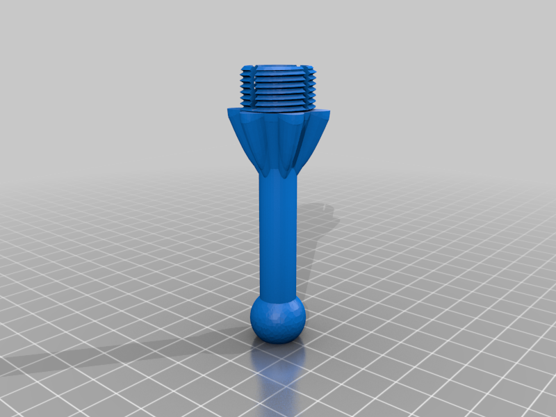 stl
stlIntermediary_Socket_-_Long_-_Small_fins.stl
538 Ko · 256 Downloads
-
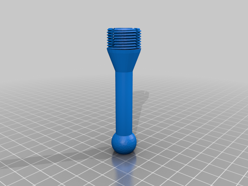 stl
stlIntermediary_Socket_-_Long.stl
419 Ko · 262 Downloads
-
 stl
stlIntermediary_Socket_-_Medium_-_Large_fins.stl
4.2 Mo · 260 Downloads
-
 stl
stlIntermediary_Socket_-_Medium_-_Medium_fins.stl
588 Ko · 257 Downloads
-
 stl
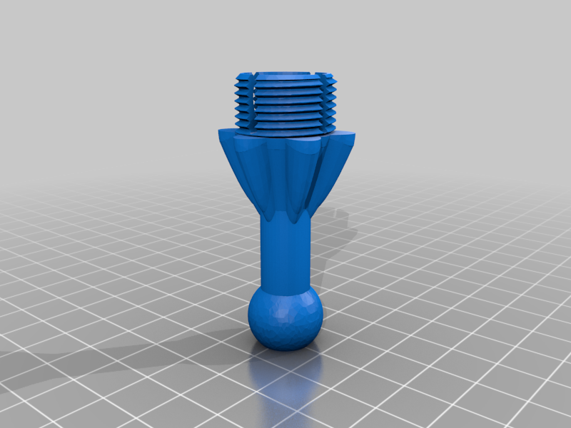
stlIntermediary_Socket_-_Medium_-_Small_fins.stl
539 Ko · 258 Downloads
-
 stl
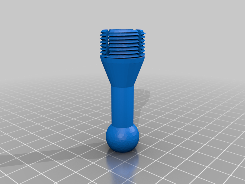
stlIntermediary_Socket_-_Medium.stl
417 Ko · 264 Downloads
-
 stl
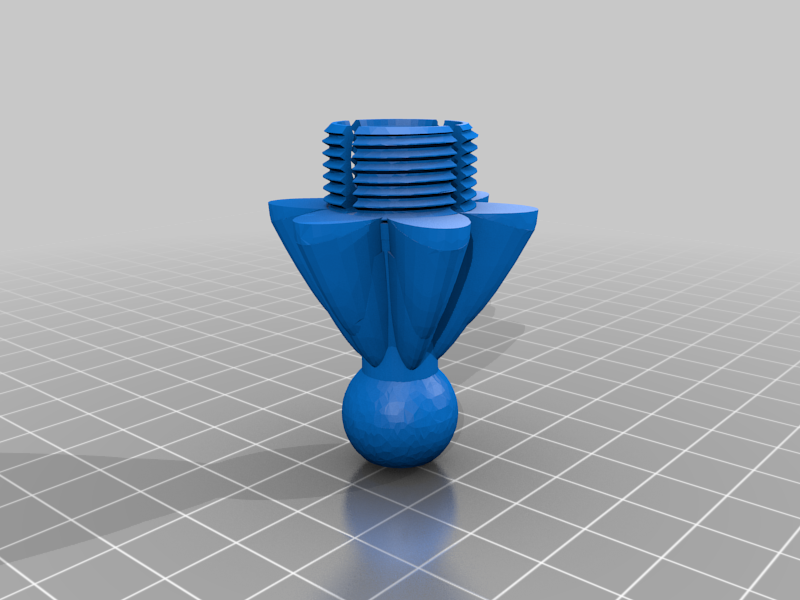
stlIntermediary_Socket_-_Short_-_Large_fins.stl
4.7 Mo · 257 Downloads
-
 stl
stlIntermediary_Socket_-_Short_-_Medium_fins.stl
586 Ko · 262 Downloads
-
 stl
stlIntermediary_Socket_-_Short_-_Small_fins.stl
541 Ko · 259 Downloads
-
 stl
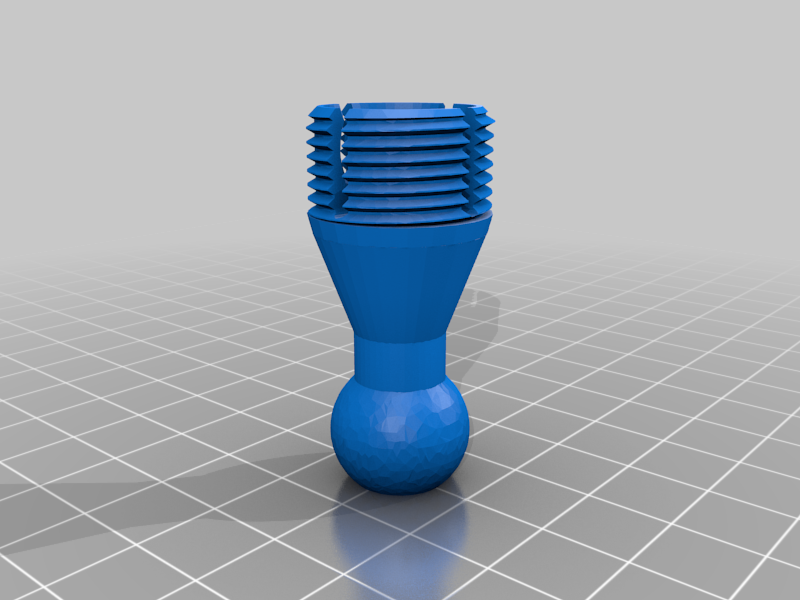
stlIntermediary_Socket_-_Short.stl
419 Ko · 265 Downloads
-
 stl
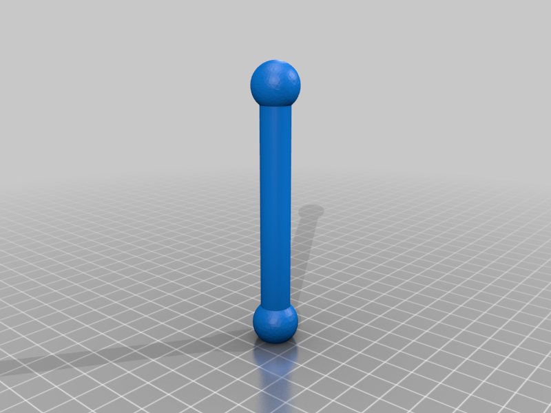
stlBall_-_Extra_Long_-_Verticle.stl
241 Ko · 265 Downloads
-
 stl
stlBall_-_Long_-_Verticle.stl
244 Ko · 266 Downloads
-
 stl
stlBall_-_Medium_-_Verticle.stl
243 Ko · 267 Downloads
-
 stl
stlBall_-_Short_-_Verticle.stl
235 Ko · 267 Downloads
Beschreibung
I enjoyed the original models, but I found that they needed to be optimized for part strength and clamping force.
The models have varying degrees of leverage knobs to allow better leverage on the tightening mechanisms.
A calibrated printer will allow for the best fit of your parts. Online printer calibration guides are invaluable and will help you get the most out of any print. Follow all of the recommendations for: E-steps, xyz calibration, flow rate, and PID tuning. These will help tremendously in helping you print functional parts.
A few drops of oil will help in parts tightening down. = )Tips:
-Use low layers heights for printing threaded parts. Depending on how large you scale your models, anywhere between 0.10mm-0.16mm layer heights will work well.
-You can increase your model scale to support greater weight.
100% can handle 1-2 ounces. (Small lights, a small webcam, a small microphone, ect.)
130% can handle a few ounces. (Smartphone, GPS, a soldering iron, ect.)
200% can hold close to a pound. (Tablets, large lights, medium rotary tools, ect.)
-Be sure to use a light coat of oil on the threads to allow for the greatest tightening strength on the ball joints.
-Weakest areas will be your shafts and rod lengths. Try to print these areas with relatively thick walls, 1.2mm-2.0mm. If you need greater durability do not underestimate the strength from increasing your part size.-The Locking nuts and flanges don't need to be nearly as strong as the longer parts do. You can print these with as little as 0.70mm walls and they will generally have enough strength to withstand the pulling forces generated by the tightening mechanism, as well as any shock generated by bumping them. Be sure to use enough infill so that layers have enough of a foundation to be formed on.
-It may help to disable "fill in gaps" and to see that "Skin Overlap Percentage" is not set too high on threaded parts as both can place "extra" material between thinner walls and make threaded areas have too much material overflow.
(A Skin overlap between 13%-15% seems to work well on my printers here, but it always helps to give a look over your models after you slice them to spot any areas where extra material might be oozed, or if there are any gaps that need to be filled in.
-Threaded parts don't really need to have gaps filled everywhere if you're using infill. This may help if you're getting over-extrusion on parts.
-Be sure to calibrate your printer. This is something that you cannot put off if you wish to have functional prints. This goes for any author's design.
Extra Notes:
Tolerances between all parts/interfaces have been reduced to 0.1mm-0.25mm. This leads to much higher frictional forces to be achieved while still allowing for some free play. The originals had a 0.5mm gap (a total of 1.0mm of free play) between the threads, which wouldn't allow parts to be tightened without the nut slipping, especially on a printer that's under extruding. Nearly every facet has either been enlarged, tightened up, and/or edited to guarantee that clamping forces will be assured and that friction on the ball sockets will be maximized.The ball/sockets were increased to 16.38mm and 16.58mm respectively. This optimizes for better use of the materials within the same working volume. Surfaces are contoured to allow a much better fit and increases frictional forces while still allowing for a reasonable amount of motion adjustment. The rods were increased to 10.57mm from 8mm, giving a much greater durability and are less likely to be snapped if bumped into. (Mistakes happen! = ) Material and volume usage has been optimized for durability, material usage, and clamping strength.
The "fins" for tightening the intermediary parts were later added as I realized that there wasn't an easy way to tighten segments by hand. I've only printed and used the largest fin segments at 200% scale, but the amount of strength that it allows enables loads of up to a pound to be suspended.
All flanges and interfaces have been tweeked and re-shaped to allow for greater grip strength and reduces chances of cracks forming around the mounting base's holes.
The 6 hole mounting flange helps to redistribute forces more evenly when needing to secure to less sturdy materials such as cardboard.
I'll add mounting flanges as I go along. Any recommendations are welcome and will be added to the project as soon as I am able. Feel free to remix! = )
I had no problems printing these with 5015 part cooling fans and at 130%-200% scale, with 0.12mm-0.18mm layer heights and up to 0.18mm-0.25mm for parts/areas without threads.100% scale may be too small to print if you're using a nozzle size larger than 0.4mm, and I never really bothered printing at that size, but this is a really good way to have multiple, small, adjustable lights! = 3
I used PETG to print these on a calibrated Mega S and a E3Pro equipped with 0.5mm nozzles. n.n