The SPACE CLOCK
 von koga73


Druckbare Dateien (3)
-
 stl
stlspace-clock_case-bottom.stl
132 Ko · 24 Downloads
-
 stl
stlspace-clock_case-face.stl
71 Ko · 22 Downloads
-
 stl
stlspace-clock_case-top.stl
185 Ko · 21 Downloads
Beschreibung
INTRODUCING THE
SPACE CLOCKALWAYS RIGHT. AUTOMAGICALLY.
What is the SPACE CLOCK ?
The SPACE CLOCK sets itself using GPS signals to achieve microsecond accuracy of up to one millionth of a second. Not only is the SPACE CLOCK a physical clock, but it also acts as an NTP server (network time server) allowing you to sync precise time across all of your network devices.
Features
- Captures
PPS (Pulse Per Second)signal fromGPS satelliteswhich marks the exact start of a second - Parses
GPS NEMAsentences which contain data includingUTC Time, Latitude / Longitude and more - Built-in
NTP Serverfor syncing network time Web interfacewith status page and configuration options (24-hour Format, Timezone, Daylight Savings)- WiFi AP mode broadcasts a
hotspotwith web interface toconnect to nearby WiFinetworks - Open-source firmware, schematics, and space-age 3D printable case
Firmware
Firmware written in MicroPython includes logic for GPS, Clock, Web interface, NTP server and more.
https://github.com/koga73/space-clock
Bill of Materials
- Raspberry Pi Pico 2 W
- Waveshare L76K GPS module
- 4-Digit 7-Segment display
- USB-C breakout board
- Solderable breadboard mini
- Tactile button 6x6x5mm
- Schottky diode 1N5817
- Female headers
- M2x4mm screws
- M3x4mm screws
Optional for GPS
- GPS antenna for housing internally
- ML1220 li-ion battery for preserving ephemeris information and hot starts
Modes
The SPACE CLOCK can operate in modes with or without a WiFi connection.
No WiFi
First boot and when no WiFi credentials are present will simply show the current time.
- Power via USB-C, will display
---- - GPS to process UTC time, will display
rising / falling animation
To connect to WiFI hold the bottom button for 3 seconds to reboot into AP Mode
WiFi Mode
If WiFi credentials are available it will attempt to connect, start web/ntp servers and then display the current time.
If WiFi fails to connect the device will reboot
- Power via USB-C, will display
---- - Connect to saved wifi, will display
wave animation - Successful WiFi connection will display
IP addressonce - Start servers for web interface and ntp
- GPS to process UTC time, will display
rising / falling animation
You can view the status page when connected via WiFi Mode
AP Mode
- Power via USB-C, will display
---- - Scan for nearby networks, will display
SCAN - Start the AP hotspot, will display the hotspot name and start the web server
- You connect to the hotspot (
space_clock) - You navigate to the default gateway (http://192.168.4.1)
- A webpage will load showing nearby WiFi networks
- You select a WiFi network and enter its password
- Device will reboot into WiFi Mode
You can view the connect to wifi page when connected via AP Mode
Configuration
The SPACE CLOCK operates on UTC Time and uses the following localized defaults which can be changed:
- 24-hour format: False
- Timezone: (GMT-05:00) America/New_York
- Daylight Savings: US/CA
You can change these settings through the configuration page when connected via WiFi Mode or AP Mode
24-hour format
The SPACE CLOCK supports displaying localized time in either 12-hour AM/PM format or 24-hour GMT/Military format
Button to change hour format
To quickly change between 12-hour / 24-hour formats just press the bottom button once
Web interface to change hour format
You can change this setting and more through the web interface when connected via WiFi Mode or AP Mode.
Timezone
GPS satellites transmit time in UTC, as such you can change the localized timezone.
Web interface to change TZ
Timezone can be set through the following selections in the web interface:
- (GMT-10:00) Pacific / Honolulu
- (GMT-09:00) America / Anchorage
- (GMT-08:00) America / Los_Angeles
- (GMT-07:00) America / Denver
- (GMT-06:00) America / Chicago
- (GMT-05:00) America / New_York
- (GMT-03:00) America / Sao_Paulo
- (GMT+00:00) UTC / Europe / London
- (GMT+01:00) Europe / Paris
- (GMT+02:00) Africa / Cairo
- (GMT+04:00) Asia / Dubai
- (GMT+09:00) Asia / Tokyo
- (GMT+10:00) Australia / Sydney
- (GMT+12:00) Pacific / Auckland
Daylight savings
GPS satellites transmit time in UTC, as such you can apply Daylight Savings with regional rules.
Web interface to change DST
Daylight Savings rules can be applied through the following selections in the web interface:
- United States / Canada
- Starts on second Sunday of March at 2am
- Ends on first Sunday of November at 2AM
- United Kingdom / European Union
- Starts on last Sunday of March at 1AM
- Ends on last Sunday of October at 2AM
- Australia
- Starts on first Sunday of October at 2am
- Ends on first Sunday of April at 3AM
Reboot
You can reboot the device by clicking the "Reboot" button in the web interface.
Reset
You can factory reset the device by clicking the "Reset" button in the web interface. This will delete your preferences and reset the device back to defaults.
Build your own!
This project can be built for around ~$50 at the time of writing
Schematic
Enable PPS on the Waveshare L76K
For the most accurate time, there is a small modification needed to the Waveshare L76K board which enables a PPS (Pulse Per Second) signal interrupt on Pin 16.
Follow the directions included in Waveshare's documentation, but essentially on the back of the board you just need to solder a 0O ohm resistor or wire across the pads for R20.
Raspberry Pi Pico 2 W
The firmware is written in MicroPython, as such you will need to follow the instructions on flashing the MicroPython runtime.
Then follow the guide to Install dependencies and official VSCode extension
To upload the code to the Pico through VSCode just open the command palette (CTRL + SHIFT + P) and select MicroPico: Upload project to Pico
Power via USB-C breakout board
I wanted the ability to power the Pico via a USB-C breakout board and it was easy enough. Just connect the VBUS/VCC + GND on the breakout board to VSYS on the Pico Pin 39 and GND to Pin 38
You should put a Schottky Diode between external power and VSYS to prevent issues if powered via Micro-USB and Externally at the same time
Display
Since this is a clock, the good ole 4-digit 7-segment display makes sense!
Wiring:
- Display GND to Pico GND
Pin 8 - Display VCC to Pico 3v3(OUT)
Pin 36 - Display DIO to Pico I2C0 SDA
Pin 6 - Display CLK to Pico I2C0 SCL
Pin 7
On my solderable breadboard I connected row 36 with row 5. On the female header I removed the pin on row 5. This allows for the 3V3(OUT) to be next to the other pins 6/7/8 needed for display.
Button
The button on the bottom allows for short presses such as to change between 12-hour / 24-hour format as well as long holds to toggle reboot of modes WiFi / AP
One leg of the button should go to GND Pin 13 / Pin 28 and the other leg should attach to GP20 Pin 26
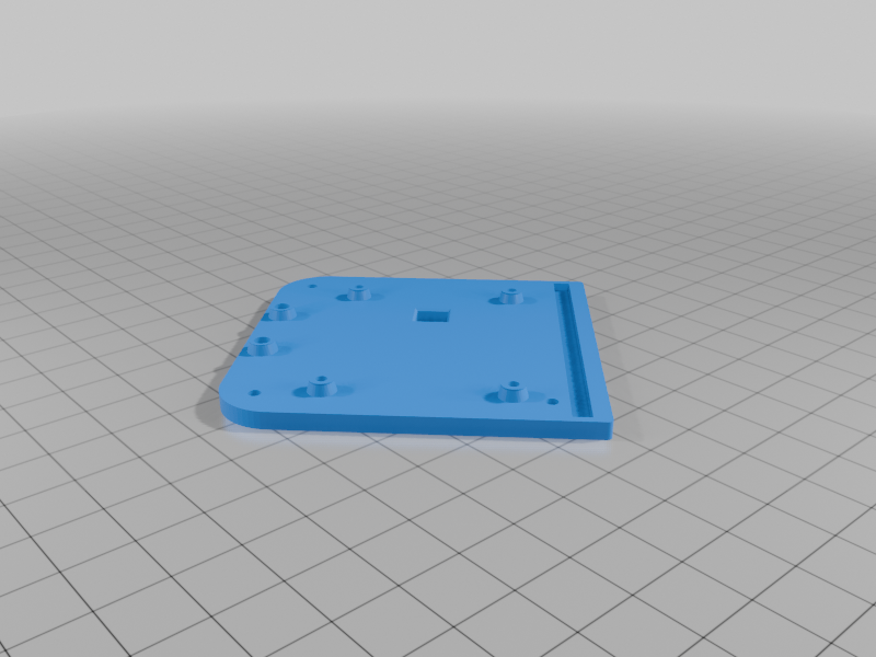
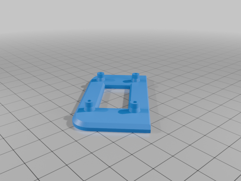
3D printed case
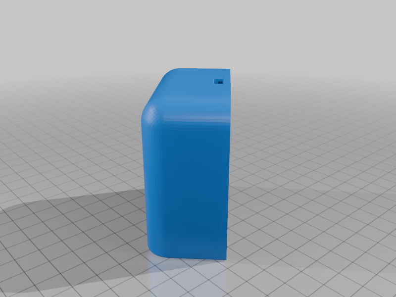
The case consists of three parts, the display mount, the bottom plate and the top cover.
- Print in PLA with or without infill.
- Print top cover vertically with support
Use the appropriate M2/M3 screws listed in the bill-of-materials to mount the boards to the respective case pieces.
SMA connector
Inside the case cover is a pre-formed 0.25in cutout for an SMA connector if you want an external GPS antenna just can drill this out with a 0.25in forstner drill bit.
If you do not want an external GPS antenna you can place a small ceramic GPS antenna internally. I stuck mine to the backside of the female headers with 3M VHB tape.
Assembly
Solder connections on the mini solderable breadboard as specified. Connect the USB-C breakout board and Display as specified. Plug the Waveshare L76K into the solderable breadboard female headers and then the Pico into the Waveshare female headers
Post your build!
If you make your own I would love to see it, post as a make or remix!
Future plans
- Automatically select Timezone and Daylight Savings via Latitude / Longitude coordinates
- Challenges with testing point in polygon timezone / region / country / state with resolutional accuracy and data size limits
Thingiverse x Raspberry Pi
This is my entry for the #PicoBuilders challenge hosted by Thingiverse in collaboration with the Rasperry Pi Foundation