PYPER - Python-Driven 3D-Printed Electric Rover


File stampabili (18)
-
 stl
stldrive_axle.stl
107 Ko · 261 download
-
 stl
stlmotor_gear.stl
48 Ko · 266 download
-
 stl
stlbearing_mount.stl
43 Ko · 255 download
-
 stl
stlmid_axle.stl
58 Ko · 255 download
-
 stl
stlhubcap_rear.stl
49 Ko · 253 download
-
stl
hubcap_front.stl
88 Ko · 256 download
-
 stl
stlmid_axle_gear.stl
124 Ko · 257 download
-
 stl
stlmid_axle_mount.stl
100 Ko · 255 download
-
 stl
stlsteering_upright_left.stl
225 Ko · 309 download
-
 stl
stlwheel_rear.stl
199 Ko · 257 download
-
stl
drive_axle_gear.stl
157 Ko · 259 download
-
 stl
stltie_rod.stl
184 Ko · 310 download
-
 stl
stlsteering_upright_right.stl
225 Ko · 319 download
-
 stl
stlwheel_front.stl
302 Ko · 267 download
-
 stl
stlbase.stl
485 Ko · 325 download
-
 stl
stltt_frame.stl
483 Ko · 264 download
-
stl
FULLY_ASSEMBLED.stl
3.9 Mo · 264 download
-
 stl
stlFULLY_ASSEMBLED_-_with_dummy_servo_and_motor.stl
4.4 Mo · 313 download
Descrizione
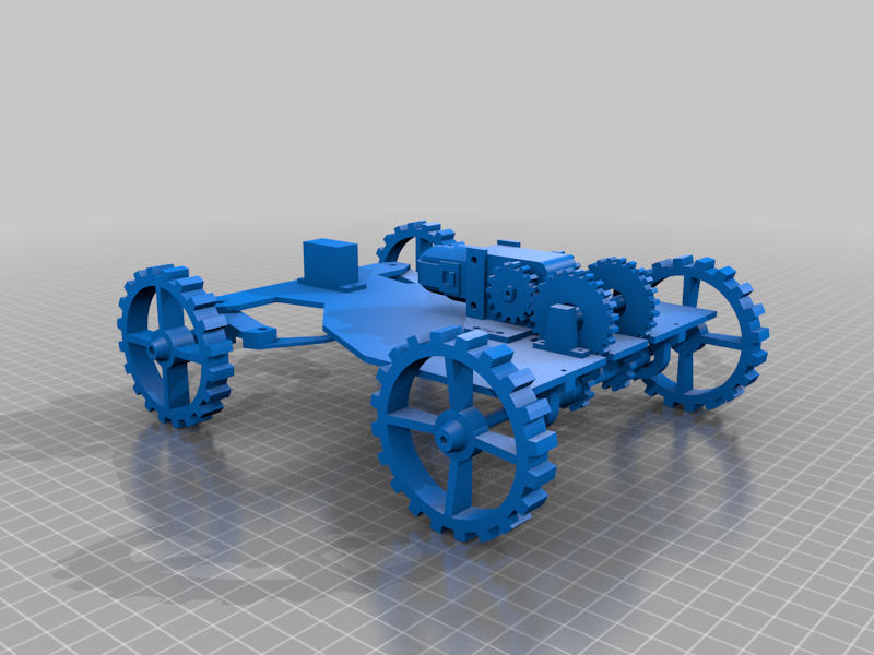
PYPER is a Python-based, 3D-Printed, Electric Rover.
I designed PYPER from scratch from the ground up - I used Blender for 3D-modeling of the chassis, steering mechanism, and drivetrain, printed the parts on my Creality Ender 3 3D Printer, designed the electrical circuitry, and wrote the code that coordinates its driving mechanics.
The project is fully open source under the Creative Commons Attribution-NonCommercial-ShareAlike 4.0 International license. The source code that runs on an onboard Raspberry Pi is available here and the 3D-printed parts (.stl files) can be found on Thingiverse here.
PYPER Specifications
- Weight, fully assembled: 23g
- Dimensions: 173x213x76 mm (WxLxH)
- Gear Ratio: PYPER uses a 48:1 TT motor (please note that, while the title of this product on Amazon states it is a 1:48 ratio, it is actually a 48:1 (reduction) gear ratio) against a 4:5 3D-printed compound gear system I developed. This graphic helped me calculate this ratio:
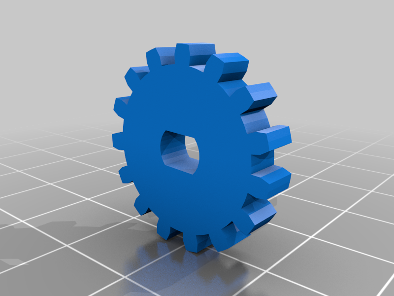
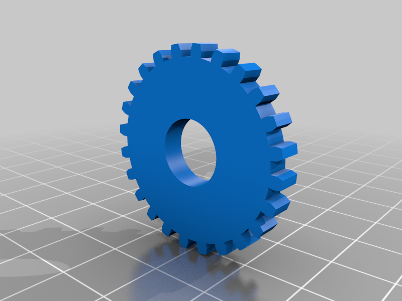
- Teeth on motor gear (gear attached to TT motor, receiving rotational input): 15
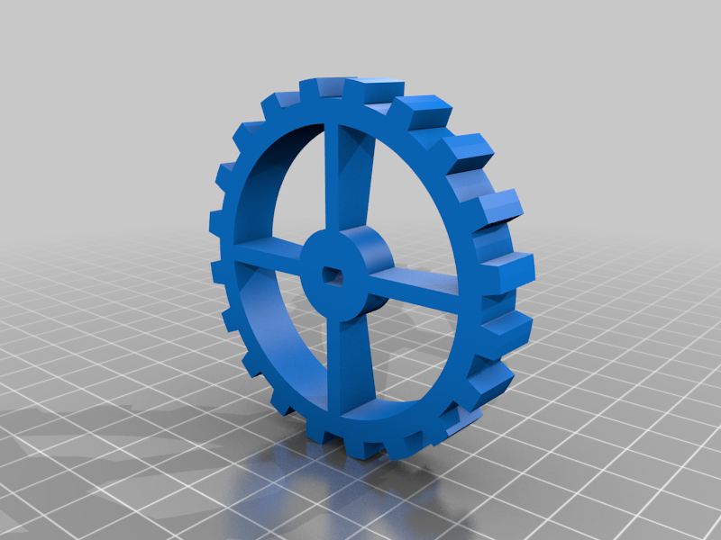
- Teeth on mid-axle gear (intermediary between motor gear and final drive shaft): 24
- Teeth on drive shaft gear: 12
- Motor Gear to Mid-Axle Gear ratio (driven / driving) = 24/15 = 24:15
- Mid-Axle Gear to Drive Shaft Gear ratio (driven / driving) = 12/24 = 12:24
- Ratio of PYPER's 3D-printed combined gear system = 24/15 * 12/24 = 288/360 = 4/5 = 4:5
- This can be interpretted as: for every 4 turns the motor gear makes (powered by the motor), the final drive shaft will rotate 5 times.
- Thus, PYPER's gear system actually speeds up the TT motor (gains speed, loses torque) a little bit.
- Altogether, combining the 48:1 ratio of the TT motor against the 4:5 ratio of PYPER's fixed 3D-printed gear system, PYPER has a 192:5 gear ratio.
- This means that pairing PYPER's 3D-printed gear system to the TT motor speeds up the TT motor slightly, gaining speed, but losing torque (going from gear ratio of 48.0 to 38.4).
Why I Designed PYPER
I built PYPER to demonstrate the essential components required to build a basic RC car: a steering mechanism and a mid-mounted motor delivering power to the rear wheels through a multi-gear drivetrain. While many other models you can find online are very impressive, they tend to be overly complex and advanced, posing challenges for beginners to mechanical engineering to understand.
In contrast, PYPER is intentionally designed to be straightforward, accessible, and approachable for anybody. So, for the sake of learning, I describe PYPER and its systems (steering, drivetrain, code, etc.) below in detail.
I hope you can learn from PYPER and uses these ideas in your own projects.
How to Assemble PYPER
You can watch the video below to see PYPER being built from the 3D-printed parts below, from the ground up. Click the image below to watch!
Parts List: What You Need to Build PYPER
PYPER is fully open source, everything you need to build one is available here. These are the parts used in PYPER, if you choose to build a PYPER yourself or repurpose these ideas in your own design:PartCost (USD)~110g of PLA filament (20% infill used)$1.761 Raspberry Pi Pico W$61 SG90 Servo Motor$1.881 TT Motor$1.471 1S Lithium Polymer Battery$6.421 MT3608 DC-DC Boost Converter$0.908 MR115-2RS (5x11x4mm) Bearings$4.271 L293D DC Brushed Motor Driver$1.251 Small Breadboard$1.7122 M2 and M3 Screws, Bolts, Washers (see below)< $2.00Misc Wires< $1.00Part costs to build PYPER: roughly $28.66.
PYPER's 3D-Printed Parts Explained
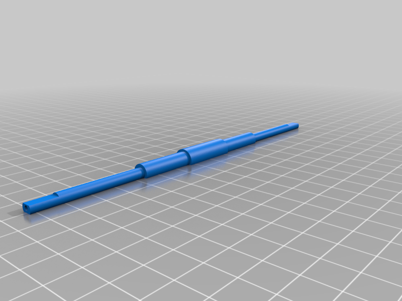
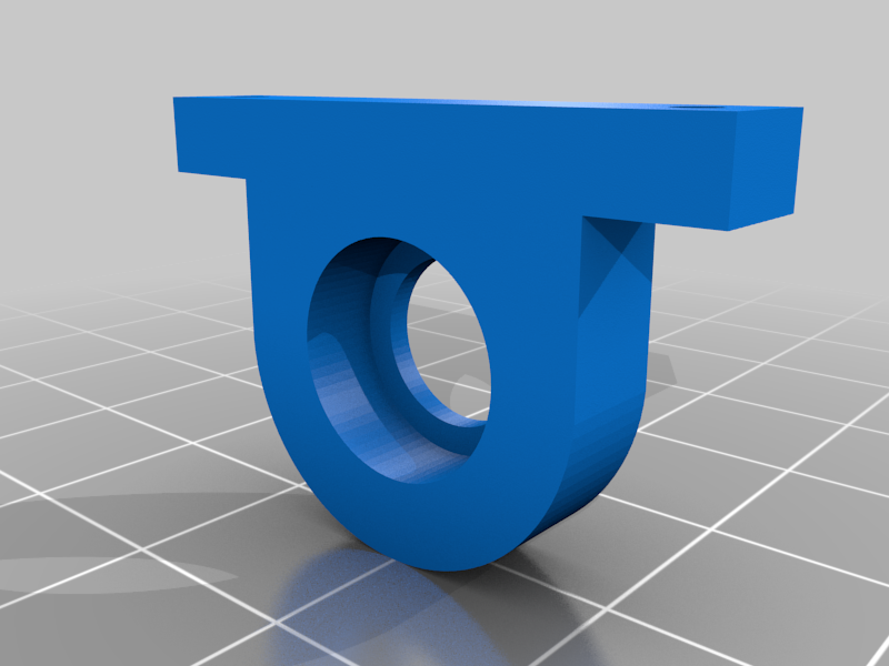
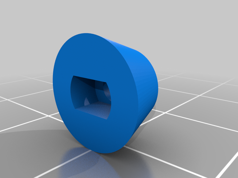
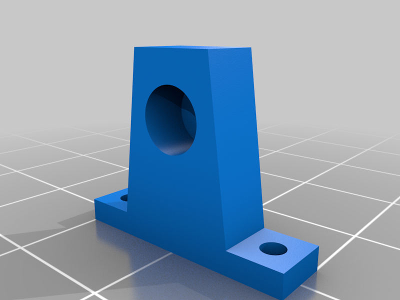
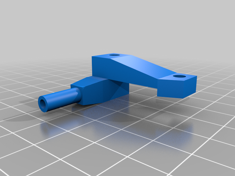
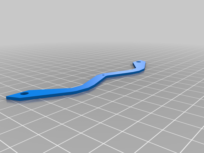
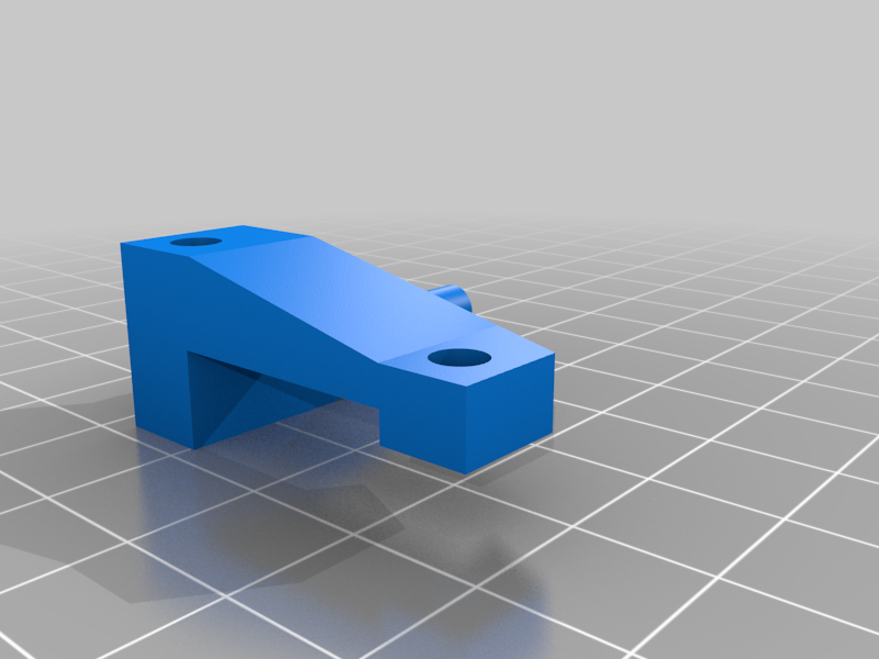
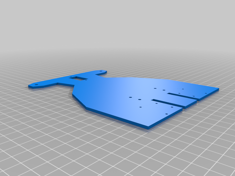
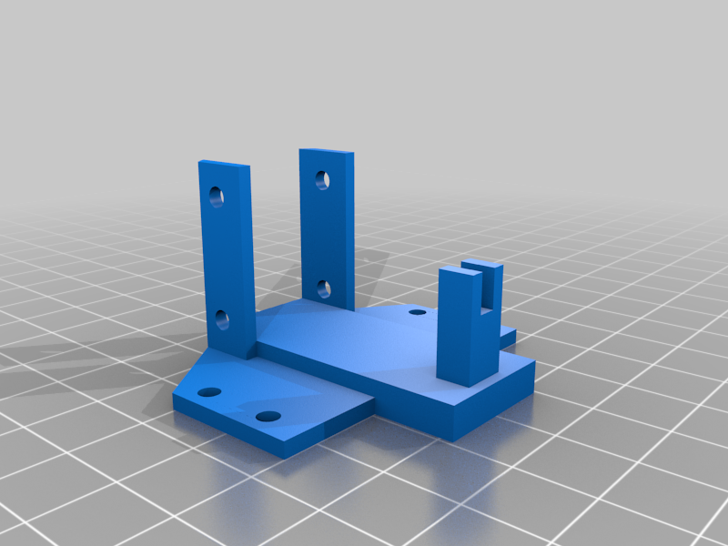
All of the 3D-printed parts needed to make PYPER are available on Thingiverse for free. Each part and its role is described below:ImagePartFunctionRolebase.stlchassisThe platform everything is built on top ofwheel_front.stlchassisThe two front wheels to the rover. PYPER's design requires two of these.wheel_rear.stlchassisThe two rear wheels to the rover. PYPER's design requires two of these.hubcap_front.stlchassisHubcap for the front wheels. PYPER's design requires two of these.hubcap_rear.stlchassisHubcap for the rear wheels. PYPER's design requires two of these.steering_upright_right.stlsteeringMounting the front right wheel to this allows the wheel to "pivot" to accommodate a steering angle, controlled by the servosteering_upright_left.stlsteeringMounting the front left wheel to this allows the wheel to "pivot" to accommodate a steering angle, controlled by the servotie_rod.stlsteeringTies the two steering uprights together, mechanically linking them together with the servo, allowing the servo to manipulate the uprightstt_frame.stldrivetrainA frame that fits around the TT motor so it can be mounted to the chassis (base)motor_gear.stldrivetrainFits snuggly around the TT motor's axle, transferring its torque into the drivetrain. PYPER's design requires two of these.mid_axle_gear.stldrivetrainMeshes against the motor_gear.stl, being driven by the motor gear. PYPER's design requires two of these.mid_axle.stldrivetrainServes to hold two mid axle gears in place along their axis, allowing them to spin freely. I recommend printing this at 100% infill to make it stronger. I have had issues with it snapping at 20% infill.mid_axle_mount.stldrivetrainHolds the mid_axle.stl in place securely, allowing the mid axle gears to mesh with both the motor gears and drive axle gears. PYPER's design requires two of these.drive_axle_gear.stldrivetrainMeshes against the two mid_axle_gear.stl, transfering torque to the final drive, turning the rear wheels. PYPER's design requires two of these.drive_axle.stldrivetrainFinal drive axle. Transfers torque from the two drive_axle_gear.stl to the rear wheels, moving the rover forward or backwardbearing_mount.stldrivetrainHolds the drive_axle.stl in place, meshing with the two mid_axle_gear.stl, and allowing it to spin freely while also supporting the weight of the chassis. PYPER's design requires two of these.Visual Depictions of PYPERS Components
These visualizations can be found in this PowerPoint deck.
Post-Printing
- You will need to insert a MR115-2RS (5x11x4mm) bearing into the following parts after printing. Each part is designed to accept the bearing with little friction, but you may need to use a mallet/hammer to bang the bearing in.
mid_axle_gear.stlbearing_mount.stlwheel_front.stl
- After printing the gears, you may need to slightly sand down some of the teeth of each gear so they mesh well against one another.
Screwing the 3D-Printed Parts Together
Metric screws are used in PYPER's design due to their wide availability, precision, and compatibility. The holes cut into the 3D-printed parts will fit are all intended for metric screws.
These are how many of each metric screw specification you'll need:Size (width*length)CountM3*30mm4M3*12mm2M3*8mm4M2*12mm4M2*8mm6M2*6mm2These are the specific needs for these screws in PYPER's design:
- 2 M3*30mm for steering uprights
- 2 M3*12mm for steering uprights
- 2 M3*8mm for screwing front wheels in
- 4 M2*12mm for screwing in final drive bearing mounts
- 4 M2*8mm for screwing in mid axle mount
- 2 M3*30mm for screwing TT motor into TT frame
- 2 M3*8mm for screwing TT frame into base
- 2 M2*6mm for screwing in rear wheels
- 2 M2*8mm for screwing in SG90 servo to frame
Wiring up the Electronics
PYPER uses:
- A 1S (1 cell) Lithium Polymer battery (but this can be swapped with any battery < 5V that can provide enough current to power these electronics, which is minimal)
- A MT3608 DC-DC converter to step up the 3.2-4.2 nominal volts of the 1 cell battery to a stable 5V
- An L293D brushed DC motor driver for controlling the application of electricity to the motor via the Raspberry Pi's GPIO pins
- A 1:48 gear ratio TT motor to turn the rear wheels, moving it forward or backward
- An SG90 servo to actuate a steering angle
- A Raspberry Pi Pico W to serve as "the brain", driving PYPER around according to requests
The components should be wired together as depicted in this wiring diagram below:
The draw.io wiring diagram can be found here, if you'd prefer to pull up a higher-resolution version.
Driving PYPER: Software
PYPER is drivable via an onboard Raspberry Pi Pico W which runs a web server on your local network and receives movement commands via HTTP requests. PYPER's software is written in MicroPython and is available in the src folder here.
Before deploying this code to your own Raspberry Pi Pico W, you will need to configure a few variables in the settings.py module:
wifi_ssid: The SSID (username) of your wifi network. The Raspberry Pi Pico will use this to connect to your wifi network and receive movement instructions via HTTP requests.wifi_password: The password to your wifi network. The Raspberry Pi Pico will use this to connect to your wifi network and receive movement instructions via HTTP requests.gp_steering: Set this to the GPIO pin (GP number, not pin number) that you are using to control the servo via the servo's signal wire. If you used the same GP pin that I used in my code, this does not need to be changed.gp_safety: Set this to the GPIO pin (GP number, not pin umber) that you have connected to the top-left pin of the L293D motor driver; this serves as the "safety" input (for the L293D to give any power to the motor, this must be set to a high state). If you used the same GP pin that I used in my code, this does not need to be changed.gp_i1: Set this to the GPIO pin (GP number, not pin number) that you are using to control one of the motor inputs (see wiring diagram). If you used the same GP pin that I used in my code, this does not need to be changed.gp_i2: Set this to the GPIO pin (GP number, not pin number) that you are using to control the other motor input (see wiring diagram). If you used the same GP pin that I used in my code, this does not need to be changed.
With the contents of the src folder loaded onto a Raspberry Pi Pico W (programs like Thonny or rshell can be used for this), once the Raspberry Pi Pico W is powered up, it will immediately begin to execute the code in the main.py module. Once the onboard LED of the Raspberry Pi Pico W goes solid, this indicates it is ready to operate!
Drive Mode
PYPER has two operation modes: HTTP mode and UDP mode. You can change which mode PYPER is in by changing the operation_mode variable in the settings.py module. 0 = HTTP mode, 1 = UDP mode.
Both operation modes are described in separate documention:
- Driving PYPER in HTTP mode
- Driving PYPER in UDP mode (coming soon!)
Clips from Development
I routinely took small clips during PYPER's development, demonstrating each part of the design. I'm listing them here for learning purposes, in case you want to study a specific piece: