
Electric Generator
 por sslivinski


Ficheiros imprimíveis (26)
-
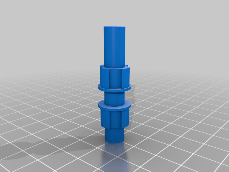 stl
stlaxel.stl
35 Ko · 273 descargas
-
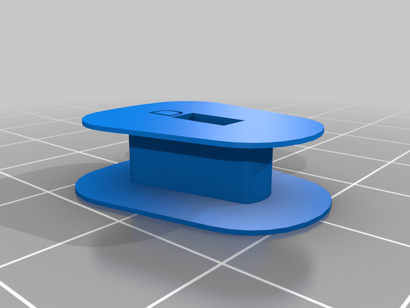 stl
stlcoil.stl
27 Ko · 280 descargas
-
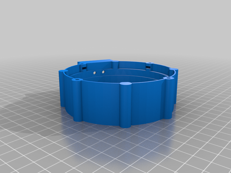 stl
stlcase_base.stl
219 Ko · 290 descargas
-
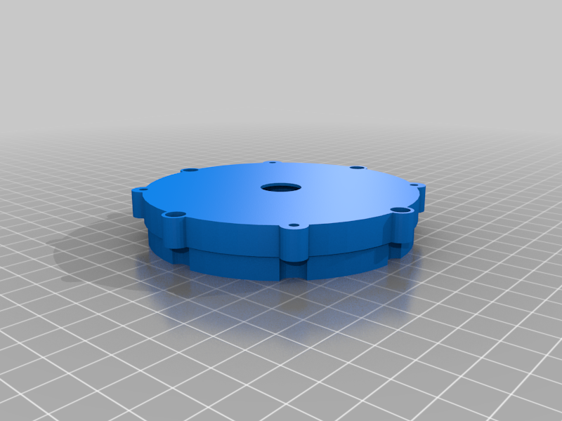 stl
stlcase_lid.stl
164 Ko · 277 descargas
-
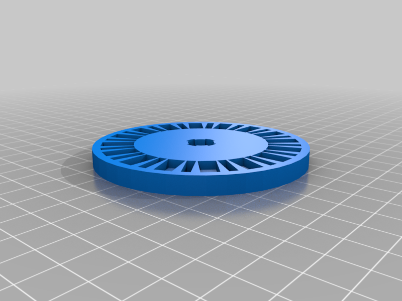 stl
stlrotor.stl
196 Ko · 293 descargas
-
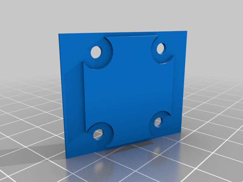 stl
stlwirebox_cover.stl
33 Ko · 271 descargas
-
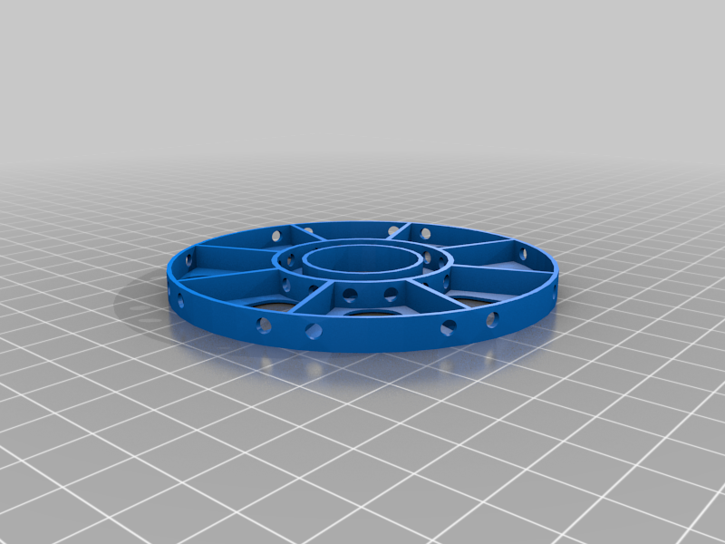 stl
stlstator.stl
530 Ko · 284 descargas
-
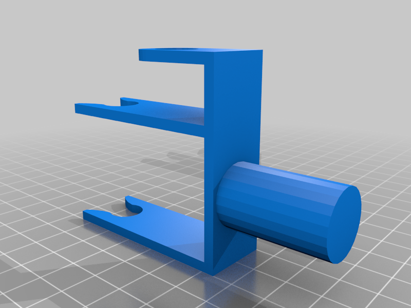 stl
stlstand.stl
28 Ko · 274 descargas
-
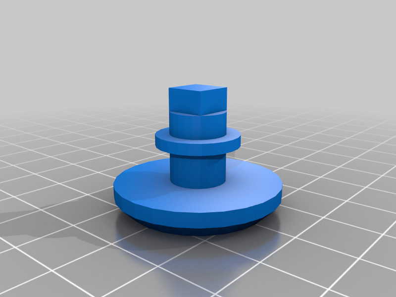 stl
stlcoil_holder_-_left.stl
29 Ko · 277 descargas
-
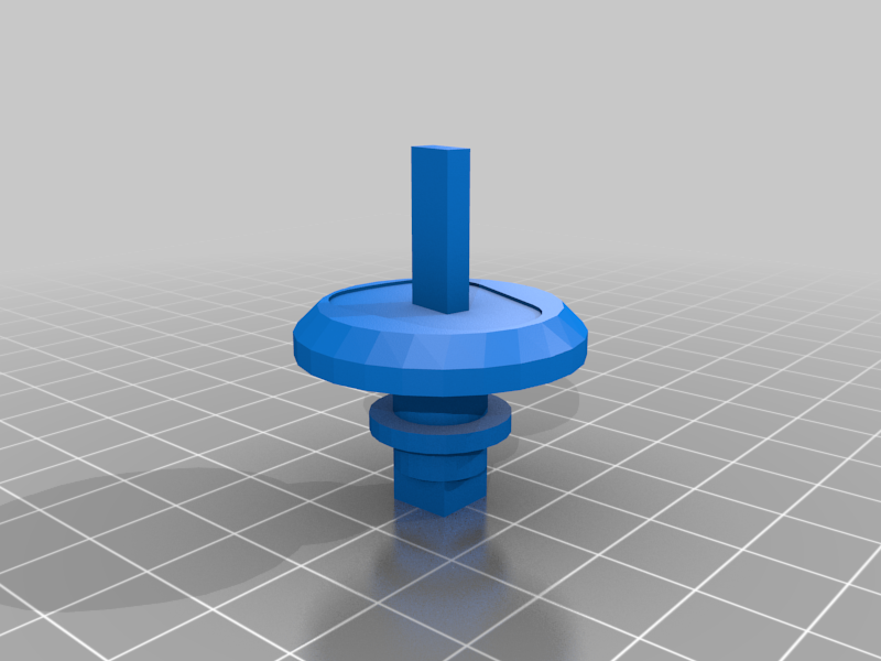 stl
stlcoil_holder_-_right.stl
29 Ko · 275 descargas
-
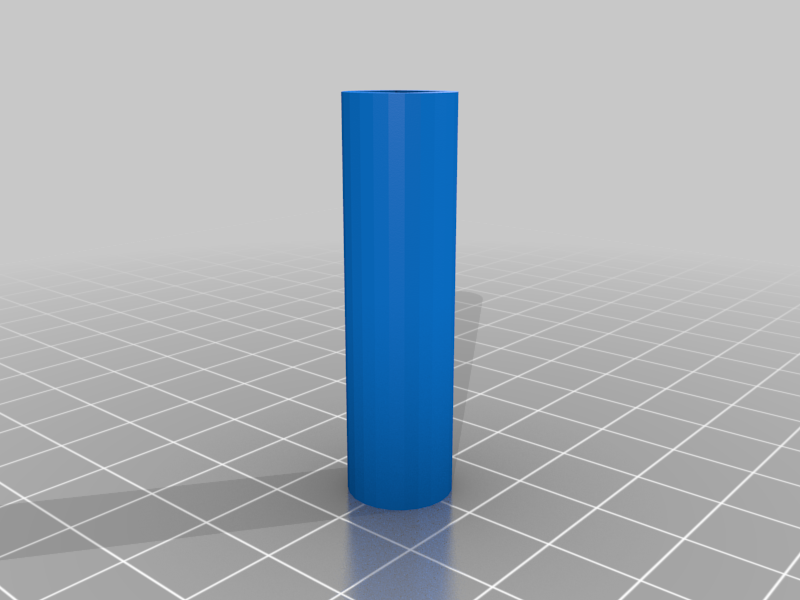 stl
stldrill_adapter.stl
8 Ko · 269 descargas
-
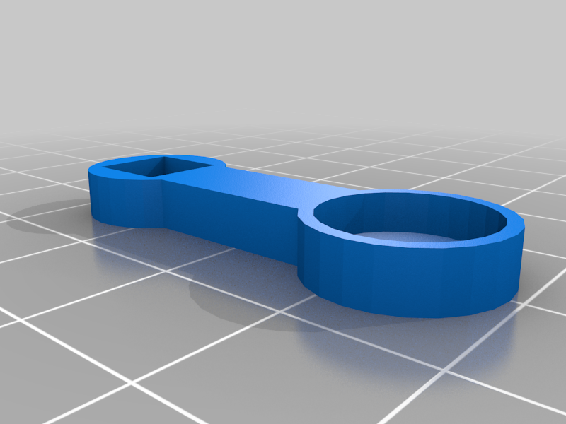 stl
stlsensor_holder.stl
19 Ko · 276 descargas
-
 stl
stlsensor_holder.stl
19 Ko · 262 descargas
-
step
case_base.step
231 Ko · 254 descargas
-
step
wirebox_cover.step
31 Ko · 246 descargas
-
step
case_lid.step
143 Ko · 248 descargas
-
step
axel.step
65 Ko · 247 descargas
-
step
stator.step
1001 Ko · 248 descargas
-
step
coil.step
110 Ko · 248 descargas
-
step
rotor.step
290 Ko · 248 descargas
-
step
coil_holder_-_left.step
40 Ko · 246 descargas
-
step
stand.step
50 Ko · 247 descargas
-
step
sensor_holder.step
19 Ko · 246 descargas
-
step
drill_adapter.step
12 Ko · 247 descargas
-
step
coil_holder_-_right.step
40 Ko · 247 descargas
-
step
sensor_holder.step
19 Ko · 242 descargas
Descrição
This is a generator I built with my daughter for her 8th grade science fair. the design below will produce 12v AC.
parts list:
2x bearings - 8x22x7mm: https://www.amazon.com/gp/product/B07V3NG2XR/ref=ppx_yo_dt_b_search_asin_title?ie=UTF8&th=1
28 gauge enameled copper wire: https://www.amazon.com/gp/product/B07DYF53ZN?th=1
32 magnets per rotor - 12 x 6 x 3mm: https://www.amazon.com/gp/product/B09L47HV7M
4x nuts - M3
4x bolts M3x12 up to M3x20 socket head screws
digital counter for the coil winding tool; https://www.amazon.com/gp/product/B08VRYFXQY
3D printing steps:
all parts were printed with PLA filament using a Prusa MK3S at 0.2mm layer height
i have included a coil rapping tool that you can use to make the coils
CASE
case base.stl: printed no supports required 0.2mm layer height
case lid.stil: printed no supports required 0.2mm layer height
ROTOR
roter.stl: print without supports, 0.2mm layer height
STATOR
stator.stl; this is what your coils will attach to, this should print with no supports
coil.stl; you need 8 of these, this needs supports to print the letter D should be facing the build plate. These are very delicate parts some of them may not print perfectly so make extras. To wind the coils you can use the coil winding tool (below)
AXEL
axel.stl; The axel needs supports to print its easiest to print standing up. it should be printed with 100% infill for strength
COIL WINDING TOOL
coil holder right.stl;
coil holder left.stl;
sensor holder.stl; attach the little magnet from the digital counter if you are using that
drill adaptor.stl;
stand.stl; attach the digital counter to the stand
Assembly Instructions:
STATOR AND COIL
to get 12v AC each coil requires 107 turns. The winding tool with the counter (see parts list) and a drill makes this a lot easier. Once you have made all 8 coils they need to be glued to the stator. each end of wire must be scrapped to remove enamel. solder the end of coil to beginning of adjacent coil in clockwise order. you should have 2 wires remaining from the last 2 adjacent coils.
NUTS
each of the 4 nuts goes into the slot of the case base
ROTOR
the axel will support 1 or 2 rotors each rotor requires 32 of the magnets, if you want to use less magnets you don't need to put the sideways ones in but those make the generator stronger. They create what is known as a halbach array (https://www.kjmagnetics.com/blog.asp?p=halbach-arrays). The face up magnets need to be oriental alternating north and south. The sideways magnets amplify the magnetic field so the poles should match the pole of a face up magnet. For example if the pole of a face up magnet is north and then the pole of the sideways magnets to the right or left is also north. They way to repel each other so this is how you will know they have the same pole. I recommend usinghttps://www.kjmagnetics.com/blog.asp?p=halbach-arrays glue to keep them into the rotor. Gorilla glue works well for this.
FINAL ASSEMBLY
- Put 1 bearing in case base and lid each
- Put 1 rotor on bottom of axel (side without notch). magnet should be facing up towards notched part of axel
- Fit axel into bearing of case base
- install stator and feed wires through holes into wire box of base
- install top rotor (if using) with magnets facing towards stator. Magnets must attract each other, otherwise change orientation.
- install lid
- attach M3 screws through lid into base and tighten