Digicomp I
 par markz


Fichiers imprimables (21)
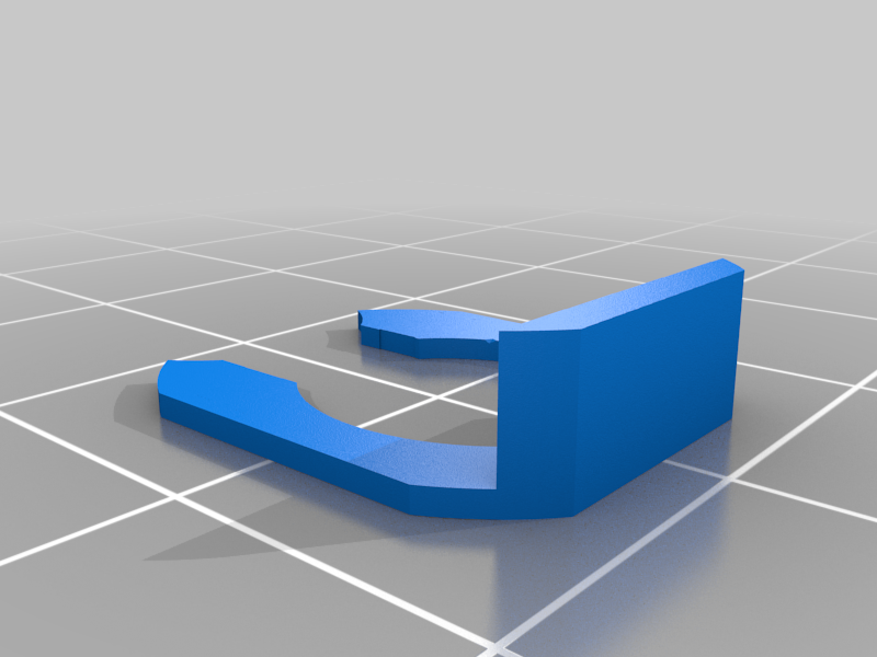
-
 stl
stlgusset.stl
850 Ko · 5 364 téléchargements
-
 stl
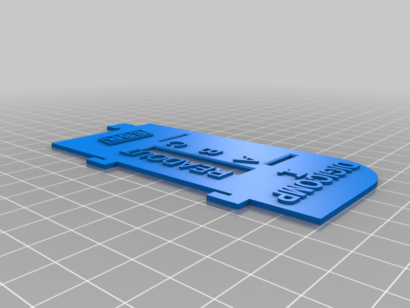
stlreadout.stl
4.1 Mo · 5 352 téléchargements
-
 stl
stlrod_bearing_plate.stl
4.7 Mo · 5 363 téléchargements
-
 stl
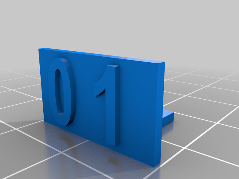
stlReadout_tab_with_digits.stl
1.2 Mo · 5 348 téléchargements
-
 stl
stlEndpiece.stl
5 Mo · 5 331 téléchargements
-
 stl
stldouble_slider.stl
179 Ko · 5 341 téléchargements
-
 stl
stlslider.stl
207 Ko · 5 328 téléchargements
-
 stl
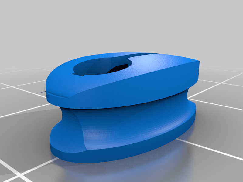
stlRubber_Band_Pully.stl
3.3 Mo · 5 347 téléchargements
-
 stl
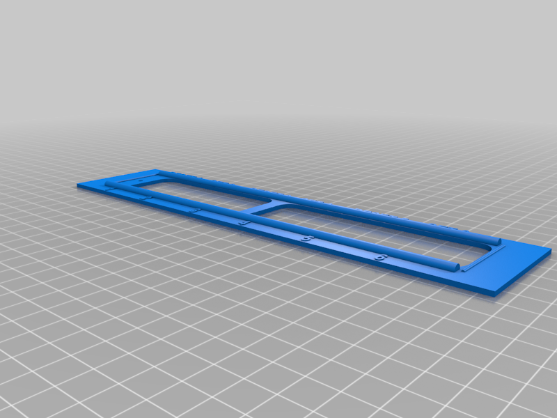
stlslider_plate.stl
5 Mo · 5 324 téléchargements
-
 stl
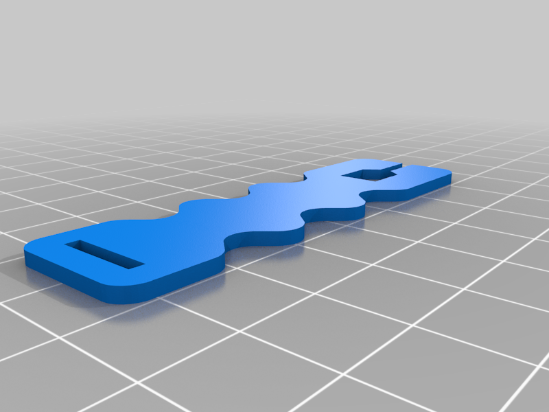
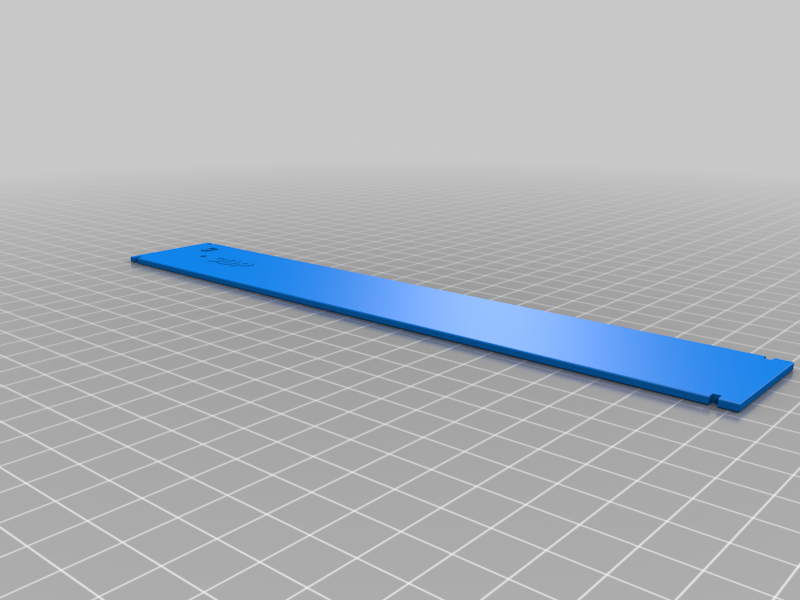
stlReadout_tab.stl
532 Ko · 5 307 téléchargements
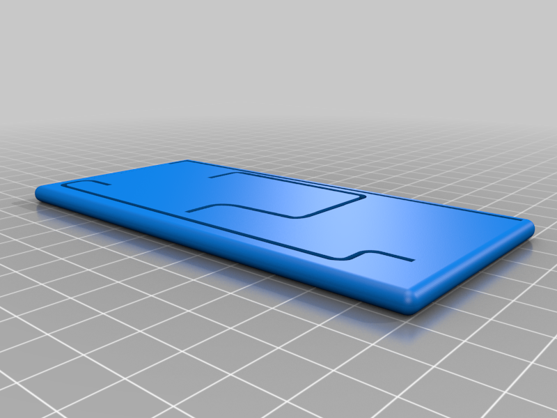
-
 stl
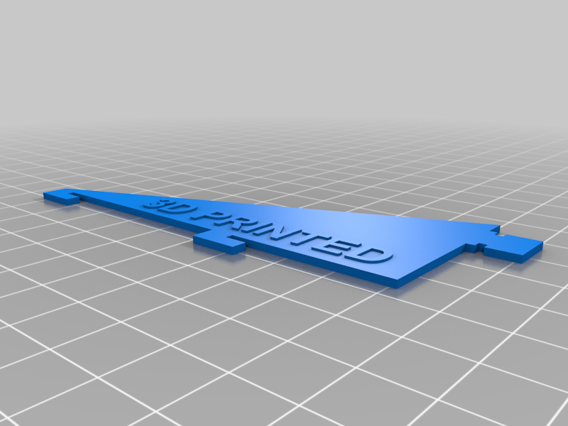
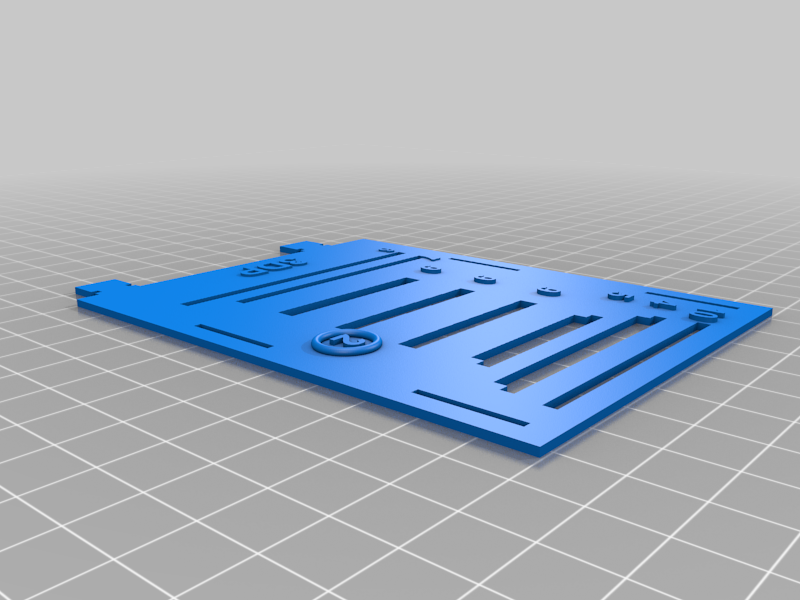
stltop_plate.stl
6.9 Mo · 5 312 téléchargements
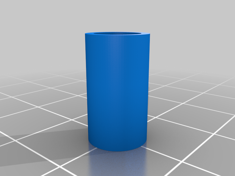
-
 stl
stlreadout_connector.stl
23 Ko · 5 312 téléchargements
-
 stl
stlBase_Clip.stl
687 Ko · 5 316 téléchargements
-
 stl
stlflipflop.stl
9.3 Mo · 5 324 téléchargements
-
 stl
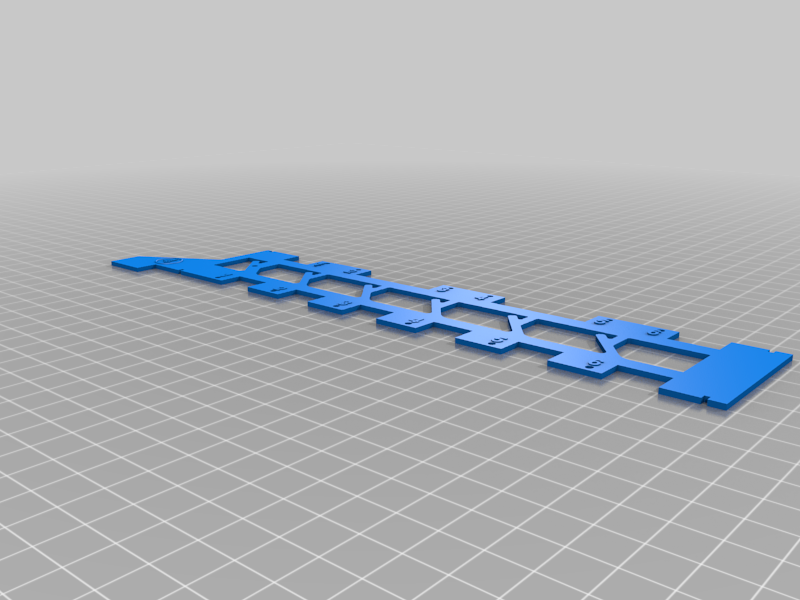
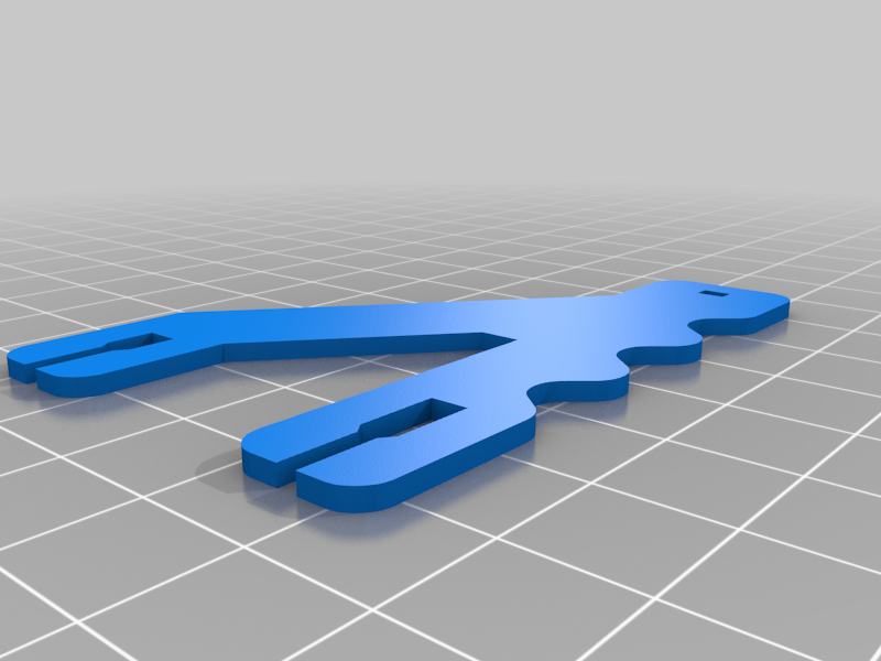
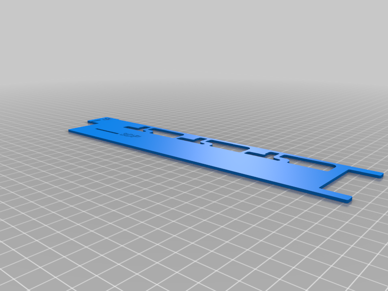
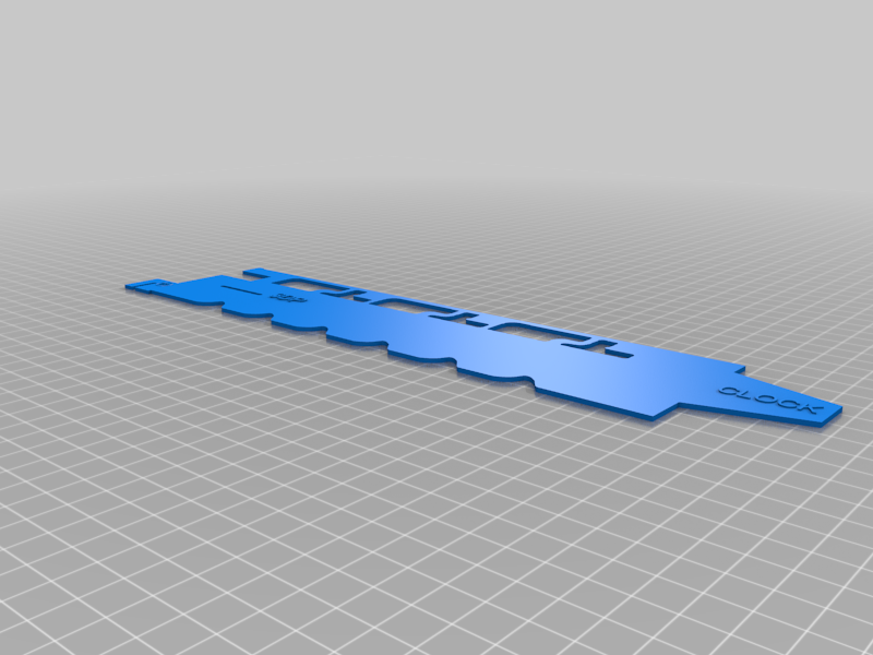
stlwire_template.stl
771 Ko · 5 314 téléchargements
-
 stl
stlstraw_short.stl
401 Ko · 5 303 téléchargements
-
 stl
stlreset_clock.stl
3.5 Mo · 5 297 téléchargements
-
 stl
stlset_clear_clock.stl
4.6 Mo · 5 287 téléchargements
-
 stl
stlbase_-_full.stl
14.5 Mo · 5 293 téléchargements
-
 stl
stlbase_modified.stl
14 Mo · 5 284 téléchargements
-
 stl
stlstraw_long.stl
516 Ko · 2 315 téléchargements
Description
Print if you wish. It works as is, but has not been tested against a vintage Digicomp I.
Testing will occur over the next couple of months.
This is a work in progress of a 3d printed recreation of the DIgicomp I, a three-bit computer from the 60's. Thanks to the members of the FriendsOfDigiComp Yahoo group for their help, and their preservation of details about this device, including drawings, photos and manuals. And of course, thanks to ESR, for their genius in creating this product way back when...
The intent of this thingy is to provide a source for those who want to print there own, or to replace missing parts for a vintage device. We'll see if this all works out.
I've finally obtained a DC I off Ebay and am currently updating parts. So far, they're very close. I'll post when complete.
OTHER SOURCES YOU SHOULD KNOW ABOUT:
Looking for a DC I that you don't have to print? Concerned about the cost to print? A wonderful, fully functional recreation of the DC I in card-stock is available from MindsOnToys: http://www.mindsontoys.com/kits.htm
Looking for a DC II ? EvilMadScientist has a beautiful recreation in wood. http://shop.evilmadscientist.com/productsmenu/tinykitlist/375-dcii
And of course, there's a DC II app for IOS devices, if I may tout my own product.
https://itunes.apple.com/us/app/virtual-dc-ii/id668402874?ls=1&mt=8
Thanks !
BUILD LIST
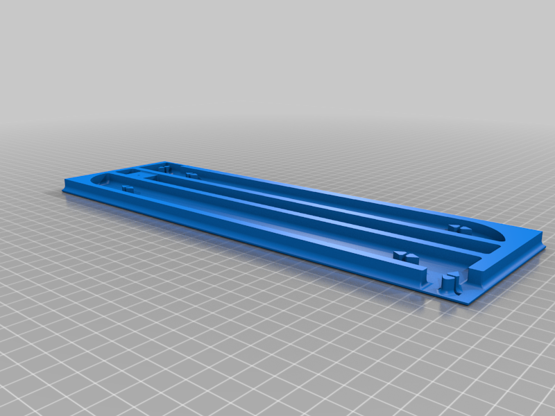
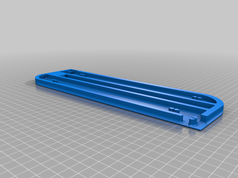
Qty-1 Color=White Full Base or Base Modified, full base similar to the original base or
modified base, with two opposite rounded corners for easier printing
Qty-2 Color=Red End-piece or End-piece reinforced
Qty-1 Color=Red Gusset
Qty-1 Color=Red Readout
Qty-3 Color=Red Flipflop
Qty-3 Color=Red Readout Tab or (in white) readout tab with raised numbers
Qty-3 Color=Red Readout Connector (or use short sections of drinking straw)
Qty-6 Color=Red Single Slider
Qty-1-2 Color=Red Double Slider - used in certain calculations
Qty-1 Color White Top Plate
Qty-1 Color White Slider Plate
Qty-1 Color White Reset Clock
Qty-1 Color White Set-Clear Clock
Qty-1 Color White Rod Bearing Plate
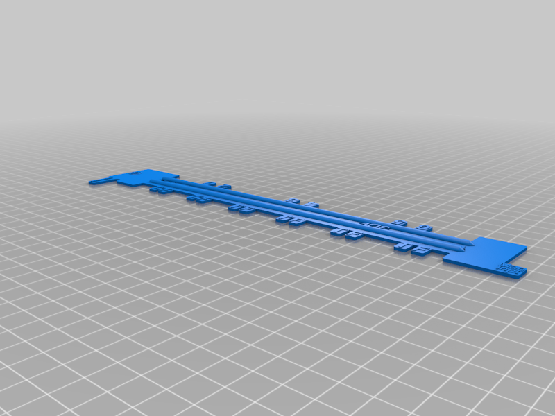
Qty-1 Any Color - wire template
Qty-6 Any Color - base Clips
Additionally:
0.055 music wire for rods
0.061 music wire for crank
number 10 rubber bands, Qty- 6
Bend 12 logic rods using the 0.55 music wire
Bend 1 crank using the 0.061 music wire.
Bend a length of wire and bend a 90 degree angle in the end to act as the pin.
Optionally:
Rubber Band Pulleys - qty 6 - my rubber bands keep popping of the top of the logic rods. (Somehow that sounds like it should be censored) So I'd have to take the top plate off, reattach the rubber bands, and put the top plate back on. Maybe I'm doing something wrong, but this got old quickly. Print the rubber band pulleys and pop one onto the top of the logic rods. Put the rubber band in the groove provided. Haven't lost a rubber band since !
BENDING INSTRUCTIONS:.
Print out the wire template, and us hand tools such as those shown in the 'wire bending tools photo'. It's tough work, but after making 12 of them, you'll have it mastered. Be sure that after bending the rod, if very close to matching the template. Try to make squarish corners, especially on top to help the rubber bands stay on. Lay the rod on the table, and make sure it lay's flat all the way from the top to the bottom, or it will cause problems later. With a nod to Norm, be sure to wear (these) safety glasses, and gloves, as music wire can split into sharp shards. Work in an open area, so the wire doesn't poke your mother-in-law or the cat in the eye. Initially, I tried cutting the wires to length but found it way easier to keep the wire longer, giving more bending leverage. Besides the printed wire template, I used a heavy set of needle nose pliers, lineman's pliers, and a mini bolt cutter for cutting the music wire. Yes, you can cut it with the lineman's plier's but it's much easier with the bolt cutter. I used http://www.amazon.com/Knipex-7101200-8-Inch-Action-Mini-Bolt/dp/B000SOSC4Y/ref=sr_1_11?s=power-hand-tools&ie=UTF8&qid=1461523354&sr=1-11&keywords=KNIPEX which I picked up at Menards.
BUILD TIPS:
1) It's important to carefully remove any overprint or schmutz. I tend to print tight on the first layer to make sure it sticks to the print bed. This causes the plastic to spread out on the first layer. This should be cleaned out especially where there is contact with other parts of the device. For instance, one problem was the slot in the front of the sliders must allow a rod to move smoothly into and out of the slot. If the rods catch in the slot the device will not function. Also on each horizontal plate, ensure the overprint is cleaned out in the slot the pin goes through. Each plate must move smoothly past the pin to their full extent without catching.
2) The rod shape has little tolerance. If the horizontal sections of a rod are too long (even slightly), the rod may not move into the correct place, especially with the clock rods.
3) At the top of the rods, where the end goes through the the rod bearing plate, the tail end of the rod may be too long and catch on the sliders. Trim off a bit of the end of the wire if necessary.
4) The crank hole in the base is intentionally tight/undersized (depending on print). It's critical that the crank does not wobble, so carefully ream out the hole just until the crank fits. A tight fit is preferred. If the crank wobbles around, the reliability or function of the device will be affected.
Progress notes:
UPDATE 5/20/16
Continuing to work on documentation at http://www.someoldguycoding.com/projects/digicomp-i/.
Device passes the check out problem from the original manual after a little tweaking.
Once documentation is complete, parts will be shipped to tester to compare against a vintage DCI. If there issues updates will be made
Thanks for your time and interest
mark-