Quadbot 17
 par m3atsauc3

Fichiers imprimables (10)
-
 stl
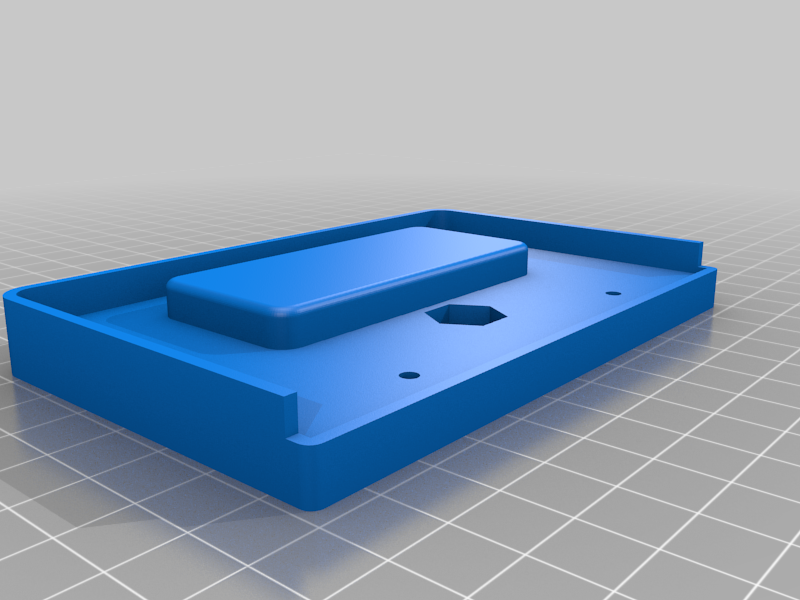
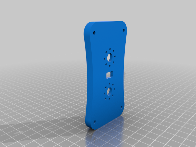
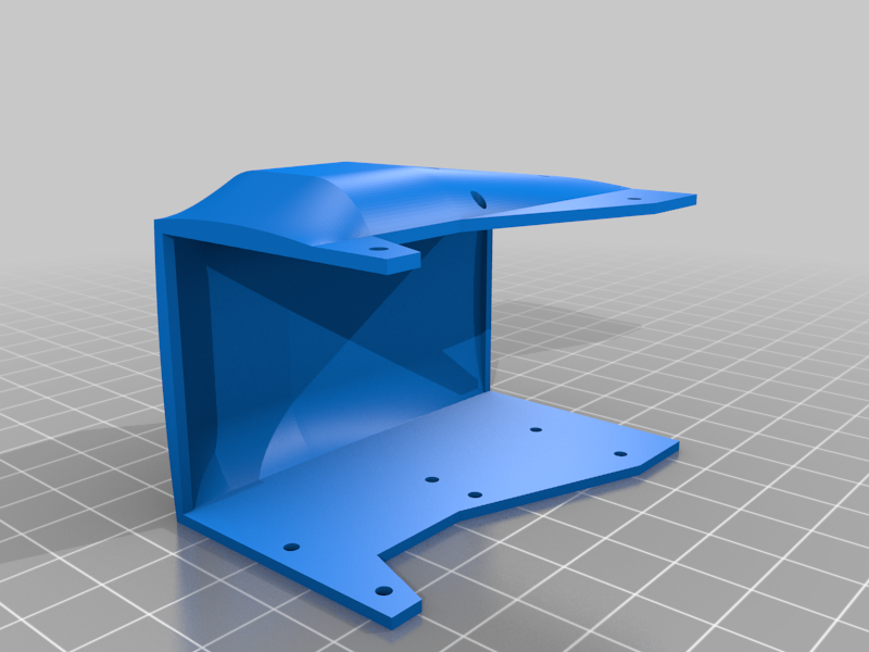
stlKinect_v2_Mount_v43.stl
152 Ko · 2 079 téléchargements
-
 stl
stlFront_Bumper_v27.stl
333 Ko · 2 057 téléchargements
-
 stl
stlRear_Bumper_v2.stl
799 Ko · 2 066 téléchargements
-
 stl
stlFoot_Base_v22.stl
314 Ko · 2 065 téléchargements
-
 stl
stlSpine_Rear_Bracket_v42.stl
348 Ko · 2 069 téléchargements
-
 stl
stlUpper_Leg_Cap_v64.stl
1 Mo · 2 067 téléchargements
-
 stl
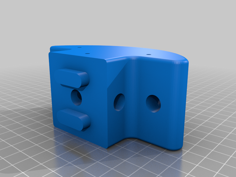
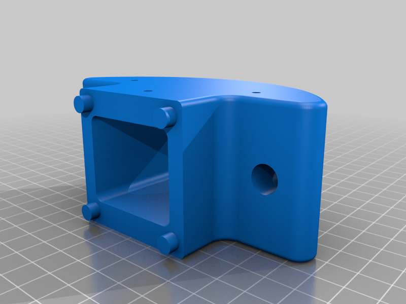
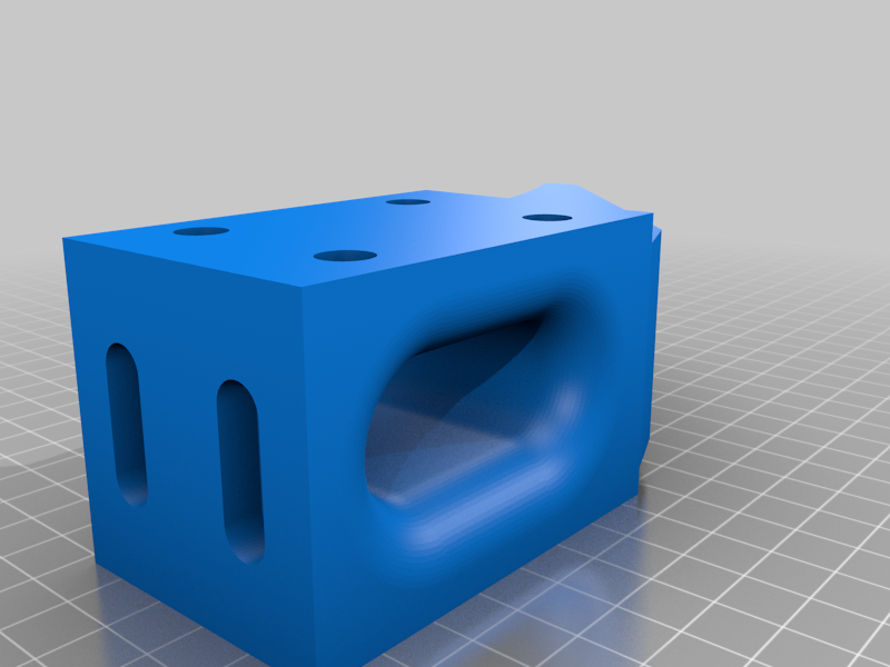
stlLeg_Base_Bracket_v28.stl
470 Ko · 2 063 téléchargements
-
 stl
stlSpine_Front_Bracket_v77.stl
895 Ko · 2 072 téléchargements
-
 stl
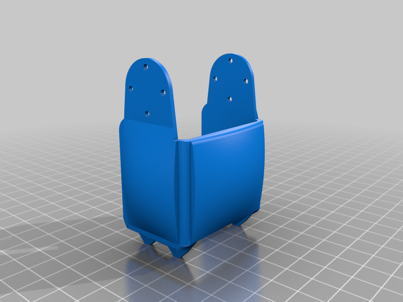
stlLower_Leg_Cap_v23.stl
618 Ko · 2 072 téléchargements
-
 stl
stlHip_Cap_v18.stl
1.1 Mo · 2 066 téléchargements
Description
This is Quadbot 17, a work-in-progress quadruped robot born out of a learning exercise in Autodesk Fusion 360.
This quadruped robot will use AX-12A Dynamixel servos (might be upgraded to the more powerful AX-18A). The legs currently have 20 DoF and there are an additional 2 DoF for the body. Servos and brackets are from the Robotis range, with some replaced by their metal counterparts available from Trossen Robotics. They will be painted to match the colour theme. The rest of the robot is designed with 3D printed parts in mind. The main framework of printed parts forming the body will be sandwiched between 1.5 mm thick custom plates.
The novel aspects of this quadruped are its articulated legs, which have higher DOF than usually found on small quadrupeds, and its articulated "spine", which will help it in navigating uneven terrain.
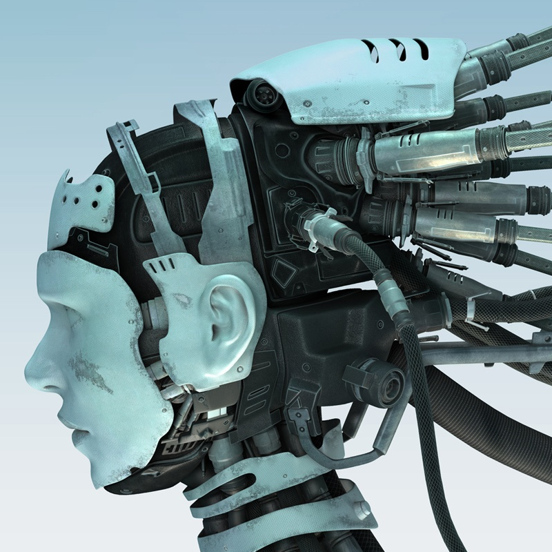
A number of options are considered for the "head", or main sensor pack: an XBOX Kinect v2 time-of-flight sensor, a Scanse Sweep LiDAR and an Intel RealSense depth-sensing camera.
Currently, a hardware test rig of one leg has been built, and the kinematics have been calculated and tested.
Update 18-12-2017
A temporary chassis has been built using MakerBeam aluminium profiles, so the next stage is to start building the CAD modelled chassis, out of aluminium sheets and 3D parts, then focusing on getting more effective walking gaits.
A walking gait has also been implemented: A Python test program reads the up/down and forward/back position of each leg for a number of frames that make up a walking gait, the IK is solved, and the resulting joint values are streamed via serial over to an Arbotix-M, which simply updates the servo goal positions.
Update 05-02-2018
The prototype custom chassis is complete!
All parts of the custom chassis have been printed in PLA plastic on a FlashForge Creator Pro. The structure is strengthened by pairs of aluminium plates. All plastic parts have been sanded and spray-painted.
I threaded the holes on all the 3D parts, which were either 3 mm wide where the aluminium plates attach, or 2 mm at the leg and spine bracket attachment points. Using a tap for the 3 mm holes worked pretty well, but the 2 mm holes were more prone to being stripped or too loose, so manually threading the holes with the bolts worked better.