SphereBot redrawn


Fichiers imprimables (15)
-
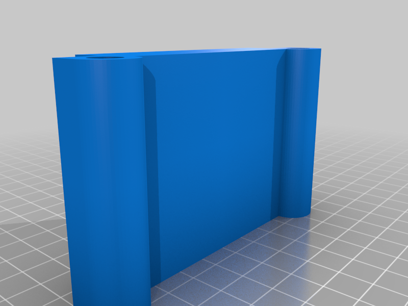
 stl
stlleft_brace.stl
14 Ko · 23 922 téléchargements
-
 stl
stlright_brace.stl
15 Ko · 23 838 téléchargements
-
 stl
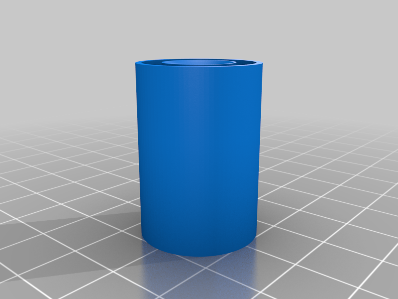
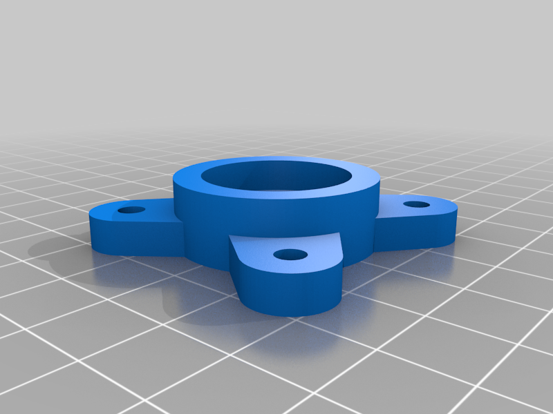
stlidler_cup.stl
149 Ko · 23 947 téléchargements
-
 stl
stldrive_cup.stl
172 Ko · 23 955 téléchargements
-
 stl
stlback_plate.stl
162 Ko · 23 851 téléchargements
-
 stl
stlpen_arm_top.stl
53 Ko · 23 921 téléchargements
-
 stl
stlend_plate.stl
111 Ko · 23 960 téléchargements
-
 stl
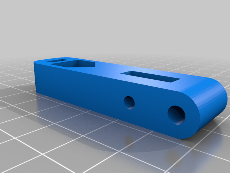
stlpen_arm_shaft_coupler.stl
65 Ko · 23 888 téléchargements
-
 stl
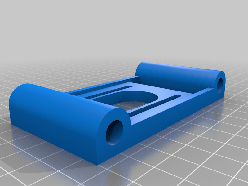
stlpen_arm_pivot.stl
44 Ko · 23 910 téléchargements
-
 stl
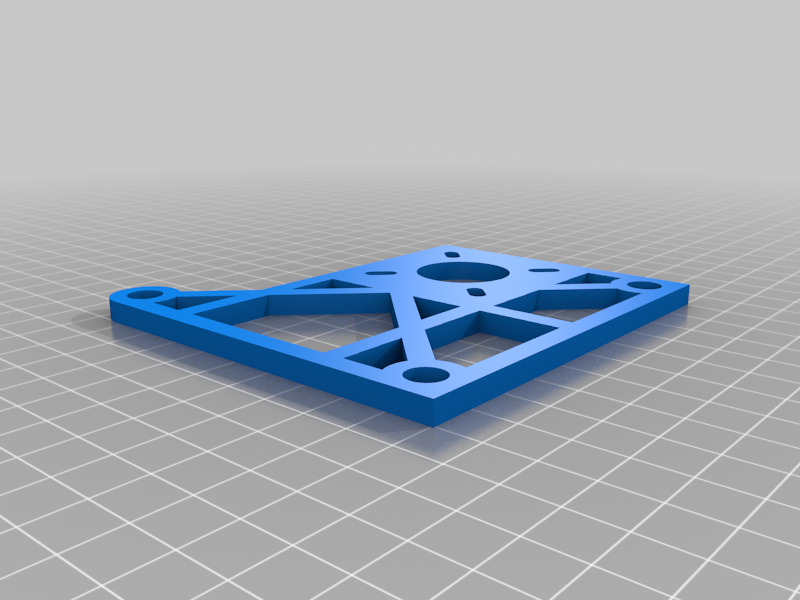
stlidler_bearing_plate.stl
92 Ko · 23 786 téléchargements
-
 stl
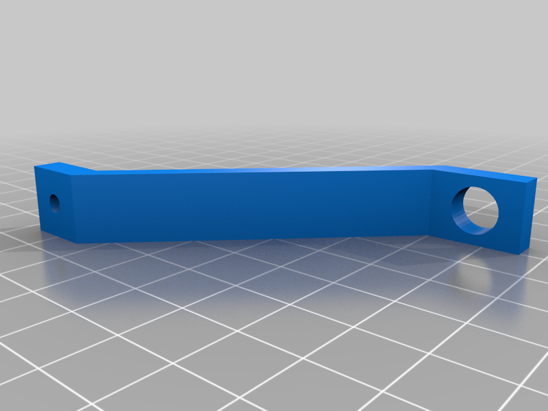
stlright_brace_v2.stl
14 Ko · 23 720 téléchargements
-
 stl
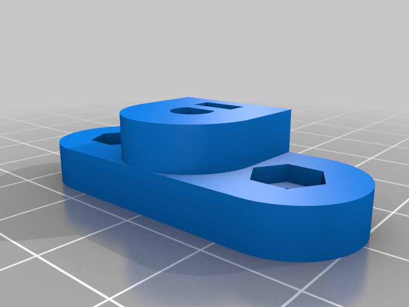
stlpen_arm_shaft_coupler_v2.stl
66 Ko · 23 767 téléchargements
-
 stl
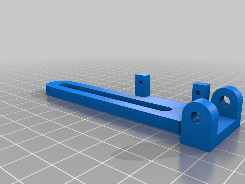
stlidler_end_plate_v2.stl
82 Ko · 23 865 téléchargements
-
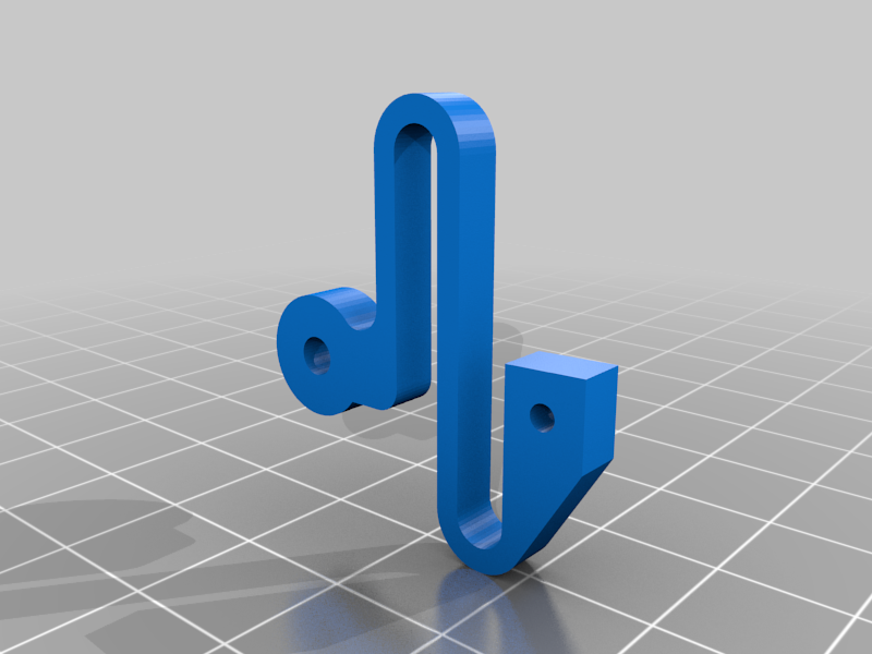 stl
stlspring.stl
44 Ko · 23 787 téléchargements
-
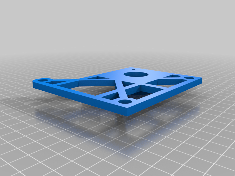
 stl
stlarduino-holder.stl
138 Ko · 23 669 téléchargements
Description
I wanted to make a few modifications to nglasson's eggbot for my own build. As a first step, I've redrawn it in Fusion 360 because I don't like working in Sketchup (sorry Sketchup fans), and Fusion's STL output is of higher fidelity. This model is mostly faithful to the original, except I've modified a few screw sizes to fix interference. I've also added the steppers, servo, and all hardware to the model assembly to help in ordering parts.
Update: v2 has a few updates and fixes:
- The pen arm shaft coupler axle hole has been resized to fit the axle on my stepper motor (5mm around, flat face inset .5mm, .1mm outside clearance).
- The outer bearing holder has been integrated into the right end plate. The idler must now be on the right, unless you mirror this, but now you can replace four long screws with one medium one. This should be printed flat side down with support for the bearing hole.
- The inner bearing hole in the end plate has been shrunk from 24mm to 22mm to fit properly.
- The slot for the brace attachment has been changed to a hole, and the right brace modified to match up.
Update: v3 now contains a pen linkage spring. I attached one end to the servo horn with a twist of wire. Also added an Arduino holder with standoffs for screws (M3x8 or #4 1/4").
BOM now under Instructions.